MultiCAD.NET API: Saving non-graphical data in .dwg drawings

customProps_en

Sooner or later every CAD application developer has to solve the problem of saving auxiliary non-graphical data in .dwg drawings. It can be attributes for a single graphical entity or layout or settings for a whole drawing.  Unlike block attributes, this data is hidden from a user and used for programmatic processing of drawings.

There are a number of ways to solve the problem, for example, adding XData objects to drawing’s entities, using XRecords objects, or creating custom non-graphical objects.

In comparison with the traditional approaches, the mechanism provided by MultiCAD.NET API is much more compact and easy-to-use. It is also unified and can be applied in the same way for different object types in a drawing: entities, layouts or a whole drawing. Using this mechanism you are able to create and save auxiliary information of any data type.

Adding custom properties to graphical objects

You can work with object custom data, using the CustomProperties property. The property is available for all child classes of McPropertySource, particularly, for all graphical entities in a database (which are instances of the McDbEntity class). CustomProperties allows writing and reading data as key-value pairs:

Data of a simple type or array of simple types can be used as a property value. However, in practice, you can add values of any type by serializing data to an array of bytes. The code below shows the example of writing a dictionary object as a value of the MyCustomProperty property:

Reading of “complex” data is also divided in two steps: reading a byte array and its subsequent deserialization. Note, that CustomProperties gets array as a List object:

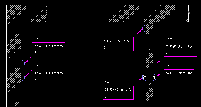
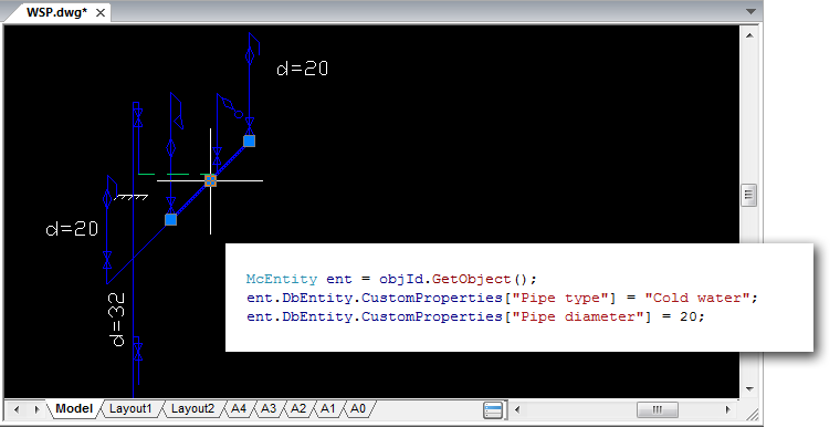
Let’s look at how the method works for a real case. Assume that there is a .dwg-file with a power supply scheme where hot and cold water pipes are represented by polylines. We are going to add a description for lines selected by a user. The description contains the information about pipe type and its diameter:

[Pipe type] = Cold Water
[Pipe diameter] = 20

Create a command that allows the user to select a polyline and then adds the key-value pairs to the selected one:

For all McPropertySource descendant classes you can also get properties of specific type (Custom, Object, User etc.) by using the GetProperties() method. The following command gets a complete list of custom properties for user selected entity and prints their names:

Adding non-graphical data to a document

The MultiCAD.NET API allows saving non-graphical data not only for entities, but also for the entire document, layouts and blocks (subdocuments). The McDocument class inherits the functionality of the base McPropertySource class and therefore you can use the same CustomProperties property to add your custom data to documents of different levels:

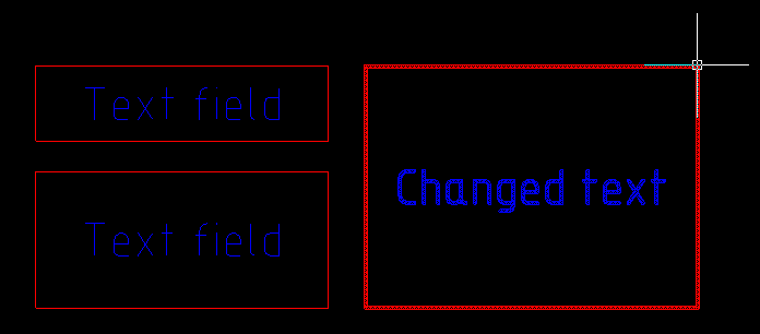
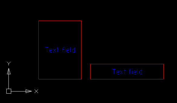
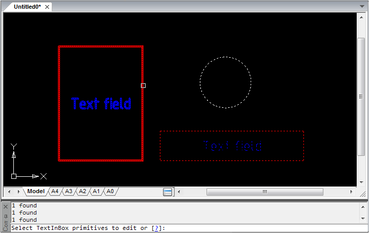
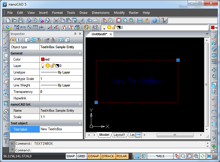
Let’s look at how it works. In one of the previous posts we talked about creating custom entities in MultiCAD.NET and dealt with the TextInBox entity that is a framed text string:

TextInBox_01_en
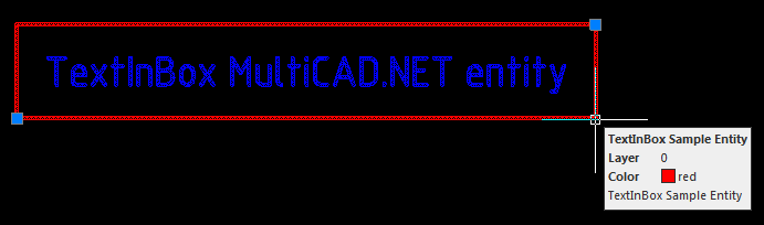
Applying custom properties to a document object, you can define its additional parameters and settings. For example, you can add properties that set colors of a frame and text string for all TextInBox entities present in the current drawing:

Overwrite the OnDraw() method from the example that is responsible for drawing an entity so that the element’s color is derived from the document custom properties:

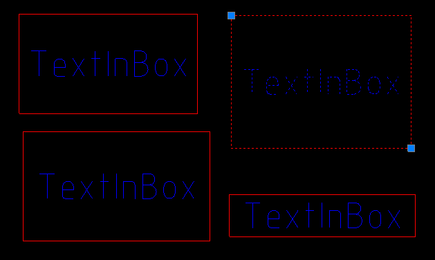
Now all added TextInBox entities are drawn in compliance with the document’s properties.

Importing coordinates from a text file to a nanoCAD drawing using the MultiCAD.NET API

importcoords_02_en

In the previous post we talked about importing point coordinates from an external text file into a .dwg drawing using classic .NET API. This post is going to describe how easy this problem can be solved using the cross-platform MultiCAD API. Here you will find the specifics of building MultiCAD application and the simple steps to launch it in nanoCAD and AutoCAD without changing project settings and rebuilding.

Creating working project

The project should be created in MS Visual Studio in the same way as it was done for the previous example:

  • Project type: Visual C#
  • Template: Class Library

To set up the project you only need to add a reference to the mapimgd.dll library that is included in the nanoCAD SDK (starting from version 4.0). The project configuration remains the same for applications that run in nanoCAD as well as in other supported CAD programs, particularly in AutoCAD. This compares to the previous project that contains two configurations — Debug NCAD and Debug ACAD. This project will use the only Debug MultiCAD configuration for all cases.

Importing coordinates and adding point entities to the drawing’s database

The structure and common code for creating application form, preview organization, and importing text data from a file remains the same. Implementation of the Importer and Creator classes was dependent on the specific host program, so they will be rewritten to be platform-independent. For example, the Creator.createPoints() method, which creates point entities by the input array of coordinates, will look as follows:

Let’s recall how the point creating procedure looks in the previous example using classic .NET API:

You can see that the number of code lines required for implementing this method has been decreased significantly. With MultiCAD.NET creating point objects, setting their coordinates and adding them to the database requires only three code lines! This is an extra advantage in addition to cross-platform support, using the API you can make application code more compact. This is carried out by “embedding” auxiliary operations into the main functionality.

Let’s look briefly at point adding procedure (a full overview will be the subject of future posts). There are three levels of geometry for entities in the MultiCAD.NET API:

  1. level of clear “math” geometry,
  2. level of geometry with primitives properties: color, linetype, lineweight etc. and
  3. level of database object.

Here we have created a DbPoint object, set its position and used the DbEntity property to move to the database level and add the point entity to the drawing’s database. Note, there is no need to determine which working space is current, the AddToCurrentDocument() method automatically finds the active document and adds an entity to currently used space.

Loading application to nanoCAD and AutoCAD

After the code is built and an application .NET assembly is generated you can load it and run in the supported CAD-programs.

  • Loading applications to nanoCAD is performed by the standard NETLOAD and APPLOAD commands.
  • To load applications to other systems, the special application called Object Enabler should be used. For example, to load an application to AutoCAD, MultiCAD Enabler for AutoCAD should be loaded first, and then use the NETLOAD command for loading your application. This standard MultiCAD Enabler for AutoCAD can be downloaded from the nanoCAD Developers’ Club.

Source code of the project is available here.

Importing coordinates from a text file to a nanoCAD drawing using the classic .NET API

importcoords_en

One of the popular questions concerning writing programs for nanoCAD is the question “how to import points from a text file to nanoCAD?”. This programming problem isn’t difficult for software developers but it can be a struggle for design engineers. That’s why we decided to write this post for beginners who are doing the first steps into the nanoCAD programming world.

Importing point coordinates to a drawing can be done using any type of nanoCAD APIs. We’ve decided to choose the .NET APIs and compare both of them; the classic .NET API and cross-CAD-platform MultiCAD.NET API. This post is the first part of this comparison that describes the point import process with the classic .NET API.

Given: a text file that contains point x-, y-, z-coordinates, one point per line. Coordinates are delimited by spaces, and a period (.) is used as a decimal point.

Required: an application with the IMPORTCOORDS command that prompts the user for a filename, imports coordinates from an input file and creates DatabaseServices.DBPoint objects in current drawing space. Point coordinates must be converted into the current user coordinate system (UCS).

Creating and setting working project

The following tools are required for developing the application:

  • nanoCAD (version 3.5 and later),
  • Microsoft Visual Studio 2008 (nanoCAD 3.5 — nanoCAD 5.0 supports loading .NET application built with .NET Framework 3.5).

It is assumed that you have a little programming experience and you are slightly familiar with C# language. If not — you are welcome to the library.

Let’s start with creating a new Visual Studio project with the following options:

  • Project type: Visual C#
  • Template: Class Library

The application that can be loaded and run in nanoCAD is a common .NET assembly (DLL). That’s why we use this template.

In the Reference tab add the following DLLs from the nanoCAD SDK:

  • hostdbmgd.dll
  • hostmgd.dll

Now all preparations are complete and we are ready to get into code writing.

Code structure

The implementation can be divided into the following steps:

  1. Register the IMPORTCOORDS command.
  2. Get the database and command line editor of the current drawing.
  3. Prompt the name of the file that contains point coordinates.
  4. Open the file and read lines with coordinates.
  5. Create DBPoint objects by the given coordinates. Transform objects coordinates from the world coordinates system (WCS) to the current user-defined coordinate system (UCS).
  6. Add created objects to current drawing space: model space or paper space.

To register the command that runs the application in nanoCAD, use the CommandMethod attribute with a name of the command before defining the method that is to be invoked by this command. Note, that the command method must be a public method:

Before we proceed with the code, let’s discuss briefly what the “database of drawing” is. Internally, .dwg file is a database with the strict hierarchical structure, where the main container objects are so called Symbol Tables that hold all database objects. It’s not only graphical objects that you can see on the drawing (lines, arcs, points, etc.), but also non-graphical objects that define contents and settings of the drawing. For example, the Layer Table contains all drawing’s layers, the Linetype Table stores all line types defined in the drawing, the UCS Table is the container for all user defined coordinate systems for this drawing and so on. Thus “to create a new object in the drawing” means to create proper database object.

At the first step we need to determine from all opened drawings the active one and obtain its database. For this purpose we will get the manager for all opened documents and then use it for getting the drawing database.

To prompt for a file, get the Editor object and call the method that gets the user input result of a specific type (file name in our case):

It’s quite easy to parse the result and get coordinates by using the C# toolsets for reading text files and processing string data:

Now we are moving to creation of graphic primitives (entities). As mentioned above, to create an object (any object, not only graphical) in the drawing, this object must be added to the drawing’s database, into a proper container object. For example, all layers are stored as records in the Layer Table. The following image illustrates the general structure of a database:

database

As for graphic primitives, they exist in a database only within separate blocks which are stored as records in the Block Table. Such an approach is an efficient way to group a number of objects to named blocks and manipulate them as single units. In other words a container object for an entity is a separate Block Table record that belongs to its parent object — the Block Table. Note also model space and paper space in the drawing are also represented by specific blocks.

Since we process the database we need to talk about data integrity. We must guarantee that its structure won’t be damaged if something goes wrong during the runtime. For security purposes the transaction mechanism is used. A transaction encapsulates a number of operations and can be treated as an entire operation. If something goes wrong then the transaction is cancelled and all the objects that have been created within the transaction will not be added to the document. If all operations inside the transaction are completely done, the transaction is committed and all objects are added to the database.

Now with this knowledge base you are able to create point entities by coordinates derived from the file and add them to the current drawing space.

The job is already done. The only condition needing to be satisfied: point coordinates must be imported to the current user-defined coordinate system (UCS). It is important to note that all entities are created and stored in a database with WCS-coordinates. So now we need to transform coordinates from the current UCS to the WCS. To perform such transformation, the UCS matrix is used as a transformation matrix:

Now the application code is done. What is next?

Loading the application to nanoCAD

It’s time to talk about how to load the application to nanoCAD. We’ve created a working project with DLL type of generated output, therefore after compiling is completed you will get the .NET assembly with the name of the project. Open nanoCAD, input the NETLOAD command and choose the generated library. Note that unlike AutoCAD, nanoCAD uses the APPLOAD command for loading applications of different types including .NET. After the DLL is successfully loaded, run the IMPORTCOORDS command to launch the application.

Importing coordinates. Version 2.0

Let’s improve the application by adding useful functionality and GUI elements.

Whereas the first version can recognize coordinates delimited by spaces (with a period as a decimal point), the second version will be able to import coordinates delimited by one of the following symbols:

  • tab,
  • space,
  • semicolon.

As for a decimal point, a comma or a period can be used; coordinates will be imported in a culture-insensitive manner. The IMPORTCOORDS command will open a modal dialog so that the user can choose the input file and proper import settings.

The import mechanism needs to be only slightly changed. However, now it should be encapsulated by the form class, and the IMPORTCOORDS handler method will be used just for creating a form object and showing it as a modal dialog:

Application form

The application form contains the following controls:

  • an open file button,
  • an open file dialog,
  • a check boxes group for choosing delimiters: tab, space, semicolon,
  • a group of radio buttons for choosing decimal separator: comma or period,
  • a text field for result preview,
  • import button,
  • cancel button.

With these controls the user is able to set all required import settings, preview import result and run coordinate import process.

ImportForm_02

Both project versions are available here.

Compatibility with AutoCAD

An application developed for nanoCAD can be easily recompiled for running in AutoCAD as well. The following steps are required:

  • Add references for the ObjectARX libraries:
    • AcDbMgd.dll
    • AcMgd.dll
  • Add the following preprocessor directives for conditional compilation:
  • Replace namespaces in the code with the proper alias defined above: Platform and PlatformDb.
  • Use the #define ACAD directive to define AutoCAD as a target platform, nanoCAD is defined by default.

Porting an ObjectARX application to nanoCAD

In this post we describe how to migrate an existing ObjectARX application to nanoCAD.

This post is part of nanoCAD SDK Documentation that can be downloaded from the nanoCAD Developers’ Club.

To migrate an existing ObjectARX project to NRX:

  1. ObjectARX projects typically contain two project configurations: Debug and Release. Open the project in Visual Studio and create additional configurations that will be used for compiling the application  for nanoCAD. For example, Debug NCAD:
    Start_NrxG_Migr_1

  2. In the General section of the project Configuration Properties set the property Character Set to the value Use Unicode Character Set and the property Use of MFC to the value Use MFC in a Shared DLL:
    Start_NrxG_Migr_2

  3. Go the C/C++ > General section and specify nanoCAD SDK header files directories in the following order:
    [nanoCAD SDK path]\include
    [nanoCAD SDK path]\include\TD
    [nanoCAD SDK path]\include\MAPI
    [nanoCAD SDK path]\include\arxgate

    Start_NrxG_Migr_3
    Note, the directories must be added in the right order to avoid compiling errors.

  4. In the C/C++ > Code Generation section choose the Multi-threaded DLL option for the Runtime Library property.
    Start_NrxG_Migr_5

  5. In the Linker > General section add paths to the nanoCAD SDK libraries:
    [nanoCAD SDK path]\lib
    [nanoCAD SDK path]\lib\TD

    Start_NrxG_Migr_6

Now it is possible to build the project, load the generated application DLL into nanoCAD with APPLOAD command and launch the application by running one of its commands.

For a complete sample project please look at the samples\NRX\CrossCircle SDK folder. This sample contains a custom entity, its managed wrapper, and commands written with both C++ and .NET.

The nanoCAD SDK is available in the nanoCAD Developers’ Club.

Creating a new project for NRX application

In this post we describe how to create a new project for NRX (nanoCAD runtime extension) applications.  NRX is a classical C++ API, compatible with ObjectARX, that allows the user to extend nanoCAD functionality.

This post is part of nanoCAD SDK Documentation that can be downloaded from the nanoCAD Developers’ Club.

To create a new NRX project:

  1. Create a new C++ project in Microsoft Visual Studio 2008 (Win32 Project):Start_NrxG_NewPrj_1
  2. Set the project name and its location:
    Start_NrxG_NewPrj_2

  3. Choose DLL as an application type and add common header files for MFC:Start_NrxG_NewPrj_21
  4. In the General section of the project Configuration Properties set the property Character Set to the value Use Unicode Character Set and the property Use of MFC to the value Use MFC in a Shared DLL:
    Start_NrxG_NewPrj_3

  5. Go to the C/C++ > General section and specify nanoCAD SDK header file directories in the following order:
    [nanoCAD SDK path]\include
    [nanoCAD SDK path]\include\TD
    [nanoCAD SDK path]\include\MAPI
    [nanoCAD SDK path]\include\nrxgate

    Start_NrxG_NewPrj_4Note, the directories must be added in the right order to avoid compiling errors.

  6. In the C/C++ > Codegeneration section choose the Multi-threaded DLL option for the Runtime Library property.
    Start_NrxG_NewPrj_5

  7. In the Linker > General section add paths to the nanoCAD SDK libraries:
    [nanoCAD SDK path]\lib
    [nanoCAD SDK path]\lib\TD

    Start_NrxG_NewPrj_6

  8. Add the following line to include the essential NRX header files:
  9. Add the following code to define an entry point:
  10. Implement the initApp() function that register all commands for the application:
  11. Implement the uninitApp() function that unloads application commands. In practice, a whole command group is unloaded, not only a separate command:

Tables in MultiCAD.NET. Part 3: Saving and loading table from an external file

Tables_21_en

The previous post about tables in MultiCAD.NET described how to create, modify and format tables with different data types and mentioned using table templates. In this post we will talk about templates and look more closely at the API that allows you to save a table to an external file as a template and then load it to the drawing to create type tables. Also the post will describe the table data exchange process between a MultiCAD.NET application and Microsoft Excel.

Example table

Let’s assume that the example table describes different types of mounting profiles (C-studs, U-channels etc.) and contains the following data: name, code, thickness, function.

Tables_12_en

Example table

We showed how to create and format tables in the previous post. Here, we’ll discuss how to save this table to an external file so that we can use it later as a template.

Saving table as a template

To save a table to a separate file, the McTable.SaveToFile() method is used. The table can be saved to a file of one of the following formats:

  • .dat files,
  • tabbed text (.txt),
  • comma-separated text,
  • XML,
  • Microsoft Excel (.xls),
  • OpenOffice.org (.ods).

The table to be saved can be picked from the drawing. The following command allows user to pick a table and save it to a file of the available formats:

Loading table from a file

To load a table from an external file, use the McTable.LoadFromFile() method. As well as for SaveToFile(), the file name can be specified explicitly or chosen from the dialog. The following file formats are supported for loading:

  • table .tbl, .dat files,
  • text (.txt, .csv, .xml),
  • Microsoft Access(.mdb, .accdb),
  • Microsoft Excel (.xls, .xlsx),
  • OpenOffice.org (.ods),
  • StarOffice (.sxc)

The following command adds a table from the user selected file to the drawing:

Now the saved table can be used as a template for adding type tables to the drawing:

Tables_13_en

Type tables based on the template table

Exchanging data with Excel

In addition to saving tables to files, MultiCAD.NET has the ability to quickly exchange data with Microsoft Excel sheets.

When the ExportToExcel() method is called, the table data is copied to a newly created and opened Excel book, keeping the cells format the same.
The following command lets the user select a table in the drawing and export it to an Excel sheet:

Also MultiCAD.NET supports importing table data from Excel. To import a selected cell range from the opened Excel sheet, use the ImportFromExcel() method:

This post concludes our review of the basic features of the tables API in MultiCAD.NET. This was definitely not the entire list of the abilities provided by the API, so if you have any questions or suggestions regarding this functionality please feel free to write comments. The tables feature list is currently being enhanced and we’ll be happy to get suggestions for more subjects to discuss in future posts.

Tables in MultiCAD.NET. Part 2: Creating and modifying

Tables_11_en

In the previous post we saw an example of using the MultiCAD.NET API for creating an automatic report with extracted properties from select drawing objects. We’ve purposely disturbed the chronological order. In today’s post we will create and modify a simple table. Then we’ll fill the table with text and numeric data, using expressions. Finally, we’ll switch over to adding blocks and subtables as cell content and conclude by attaching objects to the table to practice using their properties as the table’s dynamic contents.

Creating and formatting tables

In the MultiCAD.NET API, table entities are represented by the McTable class from the Multicad.Symbols.Tables namespace. The following code creates an empty table and  adds two rows and three columns starting at 0 index:

With the same method, you can add row and column ranges at specific positions.

Let’s add the content for the newly created table and define cell formating. The table will contain a property list of construction elements: index, name, part number, material and count. For the count column we will use a numeric cell format and the other cells will contain text data.

Tables_01_en

One of the advantages of the MultiCAD.NET table API is an ability to use different fit modes for oversized text. With the HorzFits property you can choose the following horizontal fitting options if text width exceeds cell bounds:

  • HorizontalFitsEnum.None — leave as is,
  • HorizontalFitsEnum.Shrink — adjust width factor (default mode),
  • HorizontalFitsEnum.Wrap — word wrap.

The VertFits property defines the text fitting if text height exceeds cell bounds:

  • VerticalFitsEnum.None — leave as is,
  • VerticalFitsEnum.Shrink — shrink text height (default mode),
  • VerticalFitsEnum.Expand — expand row height,
  • VerticalFitsEnum.AddRows — occupy extra rows.

After the table is created, you can modify its structure: add, delete, move or copy rows and columns. For example, let’s add one extra record for a “Bolt” component, then move the “Count” column to the last position and delete the “Index” column:

Then add a row for a total number of components. For counting, the embedded “Summ” expression can be used:

Tables_03_en

For summing up the numeric data from the cell region to the result cell, the string representation of the expression has been used. In the table editor the cell will appear as follows:

Tables_04_en

The editor can be launched programmatically using the OnEdit() method from the McTable object.

Note, that we set the numeric format for the “Count” column’s cells instead of the default Auto format, which  identifies data type automatically.

Adding tables to the drawing

The table can be added to the drawing just as other entities, using one of the following methods:

  • Table.DbEntity.AddToCurrentDocument(); — adds the table entity to the drawing. The upper left corner of the table is placed at the drawing origin.
  • Table.PlaceObject(); — inserts the table interactively, the insertion point is specified by user. Calling the method without arguments or with McEntity.PlaceFlags.Normal as a parameter value launches the table editor before inserting.

The following allows the table to be added into the drawing in the interactive mode without using the table editor:

Using blocks and subtables in cells contents

In addition to text and numeric data you can insert blocks and other tables into a table’s cells. Let’s look at how this works with a sample table that describes a metal structural profile. The first column contains the shape type, the second column: its specification, and the third column: its graphical representation:

Tables_06_1_en

The specification for the profile is represented by the following table:

Tables_05_en

Images of different shape types are represented by separate blocks stored in an external .dwg file:

Tables_06_en

Let’s discuss how we can add a profile’s specification and image to the main table.

Inserting subtables

To insert subtables, the following method is used:

McTable.InsertSubtable(ref McTable inTable, int row, int col, InsertionModeEnum mode);

  • inTable — the table to insert,
  • row, col — row and column indexes of the cell to which the subtable will be inserted,
  • mode — the insertion mode.

The subtable can be inserted in the following modes:

  • InSingleCell — the table will be inserted into the specified cell. The structure of the resulting table will be adjusted in order to fit the inserted table.
  • CellByCell — the table will be inserted cell-by-cell starting from the upper left cell. The resulting table will contain only overlapping cells from both tables.
  • Over — the table will be inserted over the main table. Neither of the  tables’ structure will be changed.

The following code inserts the specification table to a separate cell of the main table:

Tables_10_en

Using blocks as cell content

For inserting blocks into table cells, the EmbedBlock() method of a Cell object is used. This method enables embedding of a block in a separate cell using block ID, block name, or block name and name of an external file that contains the block:

bool EmbedBlock(int row, int col, McObjectId Id);
bool EmbedBlock(int row, int col, ref String name);
bool EmbedBlock(int row, int col, ref String name, ref String fileName);

The following code inserts the block of the shape’s image from the external file:

Tables_11_en

Extracting properties from entities to a table

Another useful feature of the MultiCAD.NET API is attaching entities to the table. Since the object is attached, you are able to extract its properties to a cell using special expressions. The following example demonstrates how to attach a closed polyline to the table and use its area property as a value of the cell (0,0):

Attaching objects allows you to track changes dynamically. Changing properties of the attached object changes the contents of corresponding table cells.

Tables in MultiCAD.NET. Part 1: Generating reports based on table templates

Tables_20_en

With this post, we’re beginning a series of articles about features and details of the MultiCAD.NET API for creating and modifying table entities.

For many drawings, tables are indispensable: they’re used to present descriptions, specifications, and instructions for creating construction elements represented in a drawing. It’s common to create tables based on properties extracted from drawing objects. Automating this process can save time and reduce errors.

As an example, let’s consider generating a report that contains a list of socket properties extracted from an electric map (a drawing that illustrates socket placement for a number of rooms.) Each socket is marked by a note that contains the following text data:

  • socket type,
  • code number/manufacturer,
  • room number.

Tables_14

The algorithm to create the table can be divided into three steps:

  • creating the custom report template,
  • loading the template and filling the table with data,
  • breaking the entire table into a number of pages and inserting the pages.

Creating the table template

Usually table reports are based on standard templates that are created with the tables UI. For demonstration purposes we are going to create a custom template using the MultiCAD.NET API, so that the whole table will look as follows:

Tables_15_en

Each cell value represents the number of sockets of a specific code in a specific room. Also, the table contains a page header that could be added for each page and a header for the first page with the table’s title.

Here is an example of the method that creates the template and saves it to a file with a specified name:

Users will be able to change the suggested table’s structure and cell formatting in the table editor.

This implementation of the table contains cells with special string identificators: #code and #room. These strings help to find the correct place for the data when the table is being filled. This ensures the table will be filled properly even if the numbers of rows or columns are changed.

Constructing a report

An algorithm for report building can be divided into the following steps:

  1. adding the command for creating the report
  2. selecting all the notes for multilayered constructions that contain description for sockets,
  3. loading the template and open the table editor to provide the ability to make changes in the template manually,
  4. structuring the data from the selected objects,
  5. filling in the table headers (the table’s title and column names),
  6. filling in the rows.

Here is the entire code for the example, with a discussion of key points:

Adding the command for creating the report

We will add the key method that is the handler for the smpl_CreateTableReport command and implements the algorithm:

Selecting objects

Selecting all notes for multilayered constructions can be performed using object filter:

As a result we will get an array of Ids for all notes in the drawing. Using these Ids we can obtain a text string of each note:

To simplify filling up the table, all text data should be arranged in an single structure that supports searching and sorting operations. Here the following structure of nested dictionaries is used: <product_code<room_number, count=”">>.

Loading the template

Let’s assume that the template is already created and saved to an external file (for example, C:\template.dat file) using the CreateTemplate() method. Now the saved table can be loaded using the McTable.LoadFromFile() method. Let’s create a table object, read the saved table into it and launch the table editor. It’s important to note that the table must be saved in a format that can keep the table’s structure and formatting, as well as its contents.

Tables_16_en

After that we can switch to filling up the table. The process includes sorting data received from the notes strings and adding them in appropriate cells. There is a quite wide list of possible implementations, one of which you can find in the example’s source code.

Page division

MultiCAD.NET contains an effective ability to divide a table into multiple fragments without losing its integrity. It’s used to split a large table in order to place it on a smaller sheet of paper, while still being able to edit it as a whole. To insert a page breaks by maximum page height the McTable.PagesTable.SetPageHeight() is used.

The following code fragment divides the table into separable pages so that the total height of the filled rows of each page should be less than 50 mm:

Tables_19_en

Another option is to insert a page break by a row index using the McTable.PagesTable.SetPageBreak() method. For example, to insert a page break after the row with index 7:

The result table will contain two pages:

Tables_18_en

After the table is divided, insertion points for each page need to be set. The points are set relative to the table’s insertion point using the McTable.PagesTable.SetOriginPage() method. The first parameter of the method is a page index, and the second parameter is the page insertion point. For example, to insert pages with the interval of 5:

Loading the example application to AutoCAD

Like any MultiCAD application, the example can simply run in nanoCAD after loading the example’s assembly and calling the registered smpl_CreateTableReport command. To run the MultiCAD application in AutoCAD, it’s required to use the special Object Enabler application. It’s important to note that the standard MultiCAD Enabler for AutoCAD (which is available in the nanoCAD Developers’ Club) doesn’t support objects from the Multicad.Symbols namespace. For running applications that deal with such objects, SPDS GraphiCS or MechaniCS (that contain full set of primitives including table and note entities) should be launched first.

Selecting and editing custom entities in MultiCAD.NET

00

In the previous post we discussed the process for creating custom entities in the MultiCAD.NET API, and described the CustomObjects example from the SDK. In this post we’re going to focus on the issue of selecting custom entities of the same type in the drawing.

The CustomObjects example creates custom entities that display as framed text strings:

TextInBox entities

TextInBox entities with initial text strings

We’ll extend the code for the CustomObjects example by adding functionality to searching for one or more of these entities and changing the text for each of them.

In MultiCAD.NET, when selecting a single object in the drawing, the object manager’s method SelectObject() is used. The method has the following signatures:

Both methods allow the user to select an object based on a prompt shown in the command line. The second method adds an additional parameter for the coordinates of the selection point.

For selecting multiple objects, the following methods are used:

The first method selects drawing objects using a specific filter, the second one shows a prompt in the command line and allows the user to pick objects by themself.

The filter is represented by an ObjectFilter object and defines the selection criteria: object type, documents, layers, sheets or area for searching objects. In the following example, the SelectCircles command gets a list of circle objects that are on the current sheet and intersect a specified rectangular area:

To find all circle entities from the entire drawing (not only on the current sheet), the drawing’s document should be set as a search area:

The second method allows the user to select entities manually instead of using filters, but we need to make sure the user has selected only entities of desired type.

Here we create a new command called TextInBoxEdit that allows user to select a set of any entities, then filters out only TextInBox entities from the set and changes text for all of them:

Let’s see how it works.

The command prompts the user to select entities on the drawing:

05_en

User-selected objects

After the command’s execution, the text strings have been changed in all selected TextInBox entities:

04

TextInBox entities with changed text strings

Creating custom entities in CAD with MultiCAD .NET API

One of the key disadvantages of classical .NET APIs in .dwg-compatible CAD programs is that it is impossible to create custom entities in .NET. Custom entities must be created in C++ with managed C++/CLI wrappers to be usable in .NET .

Our MultiCAD .NET technology provides the ability to create custom entities within the bounds of managed code. In addition to not requiring intermediate C++ objects, MultiCAD .NET uses standard .NET mechanisms, so there is no need to manually serialize objects, create COM objects, or perform other overhead chores that are typical with CAD programming.

The CustomObjects sample application, delivered with the SDK, provides a good example of how  MultiCAD .NET works. This application creates a custom entity, TextInBox, that draws a framed text string:

TextInBox sample entity

TextInBox sample entity

A drawing containing this custom entity can be opened by any .dwg-compatible CAD program. The entity can be modified by loading an assembly, containing the entity’s code. The same assembly can be correctly loaded to all supported CAD platforms without recompiling.

MultiCAD .NET technology runs natively in nanoCAD, and works in AutoCAD (and other compatible CAD programs) through an Object Enabler extension module, which can be downloaded in the nanoCAD Developers’ Club.

Defining a custom entity class

To create a new custom entity type, it’s necessary to define a new class, derived from McCustomBase (the base class for all custom entities.) Two attributes are required for the defined class:

  1. [CustomEntity] attribute with specified class type, its GUID, the name that will be used for all such entities in the drawing’s database and the local name,
  2. [Serializable] attribute allows for using the standard serialization mechanism from .NET Framework.

The following code defines the TextInBox custom entity class:

The methods from the base McCustomBase class for drawing entity geometry, adding into the database, selecting, and modifying the object are overridden by the TextInBox class.

Drawing geometry

The OnDraw() method is used for drawing the object. This method uses the GeometryBuilder class as a parameter.

Adding an entity into a drawing, with interactive coordinate input

The PlaceObject() method is used for adding custom entities into the drawing. Apart from its primary purpose, this method is also used for interactive coordinate input. In the MultiCAD API, interactive input is implemented in the InputJig class, which contains all essential functionality:

  • public InputResult GetPoint(string prompt) — gets a point on the drawing from user input. The prompt parameter is used to show a prompt.
  • public void ExcludeObject(McObjectId ObjectId) — excludes a specified object from snap. (This can be used to prevent an object from snapping itself.)
  • public EventHandler MouseMove — the mouse movement event handler, used for monitoring mouse motion and interactive object redrawing.

This code implements the PlaceObject method:

Editing and Modifying Object

To add object-modifying and text-editing features to the TextInBox class, the following methods from the base class are overridden:

  • public virtual List OnGetGripPoints() — get the list of object’s grip points (the marked points on the object that are used for transforming the object.)
  • public virtual void OnMoveGripPoints(List indexes, Vector3d offset, bool isStretch) — the grip points moving event handler.
  • public virtual void OnTransform(Matrix3d tfm) — defines object transformations.
  • public virtual hresult OnEdit(Point3d pnt, EditFlags lInsertType) — the object editing event handler.

This code sets the grip points to the box corner points input by the user:

When the custom entity is selected, the grip points are shown:

TextInBox_02_en

This event handler code allows the grip points to be moved by dragging:

The indexes parameter is a list of grip points indexes, and offset is a grip points displacement vector.

The OnTransform() method calculates the new positions of both corner points after transformations:

And finally, a text string editing method is required. Editing can be initiated by double-clicking on the entity, or by choosing the proper item from the context menu. Once the edit command is called, the form with text field appears to enable setting a new value for the text string:

TextInBox_03_en

TextInBox edit form

Adding Object Properties to the Property Inspector

The MultiCAD .NET API provides the ability to add the properties of a custom entity to a property inspector regardless of the platform used for opening the .dwg file, be it AutoCAD or nanoCAD. This can be done by adding the following attributes to the appropriate public property:

  • DisplayNameAttribute — defines the property name for displaying in the inspector;
  • DescriptionAttribute — property description;
  • CategoryAttribute — defines the name of the category for the property.

Use this feature to add the Text property to the properties palette:

This will display the contents of the entity’s text component in the property inspector:

TextInBox_05_en

Text property shown in the inspector

In this example, we have created a custom entity that can be added to the .dwg drawing and standard modifications for CAD users. This set of entities’ features can be extended as well. In later articles we’ll talk about creating entity versions by adding new fields and by renaming (removing) existing fields, and discuss the specifics of entity versioning in MultiCAD.NET API.