
One of the popular questions concerning writing programs for nanoCAD is the question “how to import points from a text file to nanoCAD?”. This programming problem isn’t difficult for software developers but it can be a struggle for design engineers. That’s why we decided to write this post for beginners who are doing the first steps into the nanoCAD programming world.
Importing point coordinates to a drawing can be done using any type of nanoCAD APIs. We’ve decided to choose the .NET APIs and compare both of them; the classic .NET API and cross-CAD-platform MultiCAD.NET API. This post is the first part of this comparison that describes the point import process with the classic .NET API.
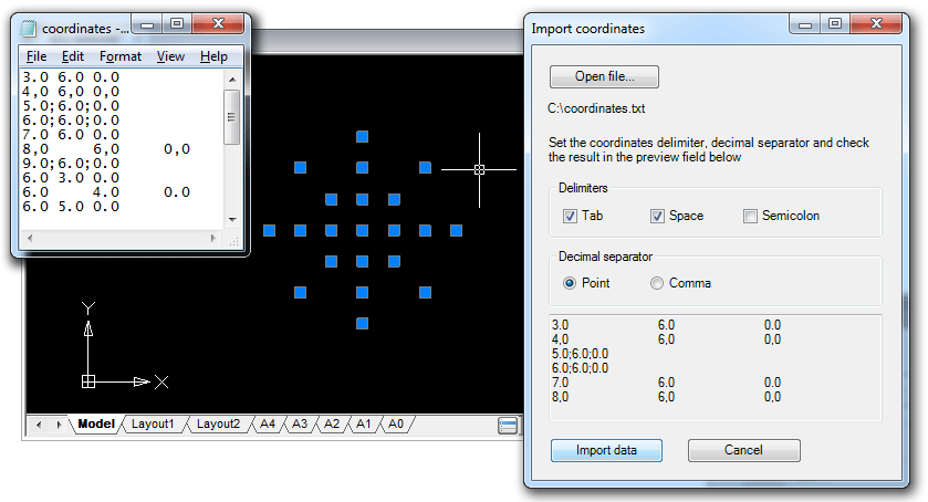
Given: a text file that contains point x-, y-, z-coordinates, one point per line. Coordinates are delimited by spaces, and a period (.) is used as a decimal point.
Required: an application with the IMPORTCOORDS command that prompts the user for a filename, imports coordinates from an input file and creates DatabaseServices.DBPoint objects in current drawing space. Point coordinates must be converted into the current user coordinate system (UCS).
Creating and setting working project
The following tools are required for developing the application:
- nanoCAD (version 3.5 and later),
- Microsoft Visual Studio 2008 (nanoCAD 3.5 — nanoCAD 5.0 supports loading .NET application built with .NET Framework 3.5).
It is assumed that you have a little programming experience and you are slightly familiar with C# language. If not — you are welcome to the library.
Let’s start with creating a new Visual Studio project with the following options:
- Project type: Visual C#
- Template: Class Library
The application that can be loaded and run in nanoCAD is a common .NET assembly (DLL). That’s why we use this template.
In the Reference tab add the following DLLs from the nanoCAD SDK:
- hostdbmgd.dll
- hostmgd.dll
Now all preparations are complete and we are ready to get into code writing.
Code structure
The implementation can be divided into the following steps:
- Register the
IMPORTCOORDScommand. - Get the database and command line editor of the current drawing.
- Prompt the name of the file that contains point coordinates.
- Open the file and read lines with coordinates.
- Create
DBPointobjects by the given coordinates. Transform objects coordinates from the world coordinates system (WCS) to the current user-defined coordinate system (UCS). - Add created objects to current drawing space: model space or paper space.
To register the command that runs the application in nanoCAD, use the CommandMethod attribute with a name of the command before defining the method that is to be invoked by this command. Note, that the command method must be a public method:
|
1 2 3 4 5 6 7 |
[CommandMethod("IMPORTCOORDS")] public void importCoords() { ... } |
Before we proceed with the code, let’s discuss briefly what the “database of drawing” is. Internally, .dwg file is a database with the strict hierarchical structure, where the main container objects are so called Symbol Tables that hold all database objects. It’s not only graphical objects that you can see on the drawing (lines, arcs, points, etc.), but also non-graphical objects that define contents and settings of the drawing. For example, the Layer Table contains all drawing’s layers, the Linetype Table stores all line types defined in the drawing, the UCS Table is the container for all user defined coordinate systems for this drawing and so on. Thus “to create a new object in the drawing” means to create proper database object.
At the first step we need to determine from all opened drawings the active one and obtain its database. For this purpose we will get the manager for all opened documents and then use it for getting the drawing database.
|
1 2 3 4 |
DocumentCollection dm = Application.DocumentManager; Database db = dm.MdiActiveDocument.Database; |
To prompt for a file, get the Editor object and call the method that gets the user input result of a specific type (file name in our case):
|
1 2 3 4 5 6 7 8 9 10 11 12 13 14 |
// Get the command line editor object Editor ed = dm.MdiActiveDocument.Editor; // An object that gets the result of user input PromptFileNameResult sourceFileName; // Print the prompt within the command line and get the result sourceFileName = ed.GetFileNameForOpen("\nEnter the name of the coordinates file to be imported:"); if (sourceFileName.Status == PromptStatus.OK) { ... } |
It’s quite easy to parse the result and get coordinates by using the C# toolsets for reading text files and processing string data:
|
1 2 3 4 5 6 7 8 9 10 11 12 13 14 15 |
// Read the file and get its content as a string array string[] lines = File.ReadAllLines(sourceFileName.StringResult); // For each string create an array of substrings delimited by space symbol, // then convert array elements to numeric value of double. string[] coord; foreach (string s in lines) { coord = s.Split(new char[] { ' ' }); double coordX = Convert.ToDouble(coord[0]); double coordY = Convert.ToDouble(coord[1]); double coordZ = Convert.ToDouble(coord[2]); } |
Now we are moving to creation of graphic primitives (entities). As mentioned above, to create an object (any object, not only graphical) in the drawing, this object must be added to the drawing’s database, into a proper container object. For example, all layers are stored as records in the Layer Table. The following image illustrates the general structure of a database:
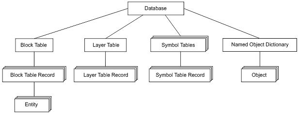
As for graphic primitives, they exist in a database only within separate blocks which are stored as records in the Block Table. Such an approach is an efficient way to group a number of objects to named blocks and manipulate them as single units. In other words a container object for an entity is a separate Block Table record that belongs to its parent object — the Block Table. Note also model space and paper space in the drawing are also represented by specific blocks.
Since we process the database we need to talk about data integrity. We must guarantee that its structure won’t be damaged if something goes wrong during the runtime. For security purposes the transaction mechanism is used. A transaction encapsulates a number of operations and can be treated as an entire operation. If something goes wrong then the transaction is cancelled and all the objects that have been created within the transaction will not be added to the document. If all operations inside the transaction are completely done, the transaction is committed and all objects are added to the database.
Now with this knowledge base you are able to create point entities by coordinates derived from the file and add them to the current drawing space.
|
1 2 3 4 5 6 7 8 9 10 11 12 13 14 15 16 17 18 19 20 21 22 |
using (Transaction tr = db.TransactionManager.StartTransaction()) { // The drawing's current space block can be directly returned from the database using the Database.CurrentSpaceId property BlockTableRecord btr = (BlockTableRecord)tr.GetObject(db.CurrentSpaceId, OpenMode.ForWrite); string[] lines = File.ReadAllLines(sourceFileName.StringResult); string[] coord; foreach (string s in lines) { coord = s.Split(new char[] { ' ' }); double coordX = Convert.ToDouble(coord[0]); double coordY = Convert.ToDouble(coord[1]); double coordZ = Convert.ToDouble(coord[2]); DBPoint point = new DBPoint(new Point3d(coordX, coordY, coordZ)); btr.AppendEntity(point); tr.AddNewlyCreatedDBObject(point, true); } btr.Dispose(); tr.Commit(); } |
The job is already done. The only condition needing to be satisfied: point coordinates must be imported to the current user-defined coordinate system (UCS). It is important to note that all entities are created and stored in a database with WCS-coordinates. So now we need to transform coordinates from the current UCS to the WCS. To perform such transformation, the UCS matrix is used as a transformation matrix:
|
1 2 3 4 |
Matrix3d ucsMatrix = ed.CurrentUserCoordinateSystem; point.TransformBy(ucsMatrix.Inverse()); |
Now the application code is done. What is next?
Loading the application to nanoCAD
It’s time to talk about how to load the application to nanoCAD. We’ve created a working project with DLL type of generated output, therefore after compiling is completed you will get the .NET assembly with the name of the project. Open nanoCAD, input the NETLOAD command and choose the generated library. Note that unlike AutoCAD, nanoCAD uses the APPLOAD command for loading applications of different types including .NET. After the DLL is successfully loaded, run the IMPORTCOORDS command to launch the application.
Importing coordinates. Version 2.0
Let’s improve the application by adding useful functionality and GUI elements.
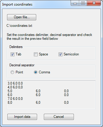
Whereas the first version can recognize coordinates delimited by spaces (with a period as a decimal point), the second version will be able to import coordinates delimited by one of the following symbols:
- tab,
- space,
- semicolon.
As for a decimal point, a comma or a period can be used; coordinates will be imported in a culture-insensitive manner. The IMPORTCOORDS command will open a modal dialog so that the user can choose the input file and proper import settings.
The import mechanism needs to be only slightly changed. However, now it should be encapsulated by the form class, and the IMPORTCOORDS handler method will be used just for creating a form object and showing it as a modal dialog:
|
1 2 3 4 5 6 7 8 |
[CommandMethod("IMPORTCOORDS")] public void importCoords() { Form form = new ImportForm(); HostMgd.ApplicationServices.Application.ShowModalDialog(form); } |
Application form
The application form contains the following controls:
- an open file button,
- an open file dialog,
- a check boxes group for choosing delimiters: tab, space, semicolon,
- a group of radio buttons for choosing decimal separator: comma or period,
- a text field for result preview,
- import button,
- cancel button.
With these controls the user is able to set all required import settings, preview import result and run coordinate import process.
Both project versions are available here.
Compatibility with AutoCAD
An application developed for nanoCAD can be easily recompiled for running in AutoCAD as well. The following steps are required:
- Add references for the ObjectARX libraries:
- AcDbMgd.dll
- AcMgd.dll
- Add the following preprocessor directives for conditional compilation:
12345678910111213141516171819#if ACADusing Autodesk.AutoCAD.ApplicationServices;using Autodesk.AutoCAD.DatabaseServices;using Autodesk.AutoCAD.EditorInput;using Autodesk.AutoCAD.Geometry;using Autodesk.AutoCAD.Runtime;using Platform = Autodesk.AutoCAD;using PlatformDb = Autodesk.AutoCAD;#elseusing HostMgd.ApplicationServices;using HostMgd.EditorInput;using Teigha.DatabaseServices;using Teigha.Geometry;using Teigha.Runtime;using Platform = HostMgd;using PlatformDb = Teigha;#endif - Replace namespaces in the code with the proper alias defined above:
PlatformandPlatformDb. - Use the
#define ACADdirective to define AutoCAD as a target platform, nanoCAD is defined by default.