
In the previous post we saw an example of using the MultiCAD.NET API for creating an automatic report with extracted properties from select drawing objects. We’ve purposely disturbed the chronological order. In today’s post we will create and modify a simple table. Then we’ll fill the table with text and numeric data, using expressions. Finally, we’ll switch over to adding blocks and subtables as cell content and conclude by attaching objects to the table to practice using their properties as the table’s dynamic contents.
Creating and formatting tables
In the MultiCAD.NET API, table entities are represented by the McTable class from the Multicad.Symbols.Tables namespace. The following code creates an empty table and adds two rows and three columns starting at 0 index:
|
1 2 3 4 5 6 |
McTable Table1 = new McTable(); int rowCount = 4; int colCount = 5; Table1.Rows.AddRange(0, rowCount + 1); Table1.Columns.AddRange(0, colCount); |
With the same method, you can add row and column ranges at specific positions.
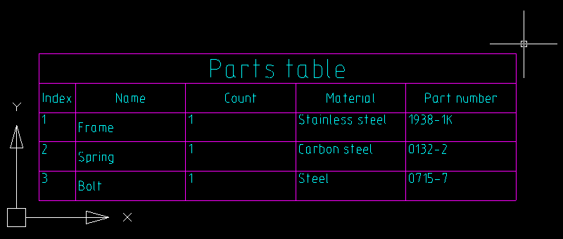
Let’s add the content for the newly created table and define cell formating. The table will contain a property list of construction elements: index, name, part number, material and count. For the count column we will use a numeric cell format and the other cells will contain text data.
|
1 2 3 4 5 6 7 8 9 10 11 12 13 14 15 16 17 18 19 20 21 22 23 24 25 26 27 28 29 30 31 32 33 34 35 36 37 38 39 40 41 42 43 44 45 |
// Sets color and text height that will be used for all table cells by default: Table1.DefaultCell.TextHeight = 2.5; Table1.DefaultCell.TextColor = System.Drawing.Color.Aqua; // The first row is the title, let's merge all its cells and set text alignment and height System.Drawing.Rectangle rect = new System.Drawing.Rectangle(0, 0, colCount - 1, 0); Table1.Merge(rect); Table1[0, 0].HorizontalTextAlign = HorizTextAlign.Center; Table1[0, 0].VerticalTextAlign = VertTextAlign.Center; Table1[0, 0].TextHeight = 5; // Fills up the table foreach (var cell in Table1.Rows[2].Cells) { cell.VerticalTextAlign = VertTextAlign.Center; cell.HorizontalTextAlign = HorizTextAlign.Center; } Table1.Columns[0].Width = 10; Table1[0, 0].Value = "Parts table"; Table1[1, 0].Value = "Index"; Table1[1, 1].Value = "Name"; Table1[1, 2].Value = "Count"; Table1[1, 3].Value = "Material"; Table1[1, 4].Value = "Part number"; Table1[2, 0].Value = "1."; Table1[2, 1].Value = "Frame"; Table1[2, 2].Type = CellFormatEnum.Number; Table1[2, 2].Value = "1"; Table1[2, 3].Value = "Stainless steel"; Table1[2, 4].Value = "1938-1K"; Table1[3, 0].Value = "2."; Table1[3, 1].Value = "Spring"; Table1[3, 2].Type = CellFormatEnum.Number; Table1[3, 2].Value = "1"; Table1[3, 3].Value = "Carbon steel"; Table1[3, 4].Value = "0132-2"; Table1[4, 0].Value = "3."; Table1[4, 1].Value = "Bolt"; Table1[4, 2].Type = CellFormatEnum.Number; Table1[4, 2].Value = "1"; Table1[4, 3].Value = "Steel"; Table1[4, 4].Value = "0715-7"; |
One of the advantages of the MultiCAD.NET table API is an ability to use different fit modes for oversized text. With the HorzFits property you can choose the following horizontal fitting options if text width exceeds cell bounds:
HorizontalFitsEnum.None— leave as is,HorizontalFitsEnum.Shrink— adjust width factor (default mode),HorizontalFitsEnum.Wrap— word wrap.
The VertFits property defines the text fitting if text height exceeds cell bounds:
VerticalFitsEnum.None— leave as is,VerticalFitsEnum.Shrink— shrink text height (default mode),VerticalFitsEnum.Expand— expand row height,VerticalFitsEnum.AddRows— occupy extra rows.
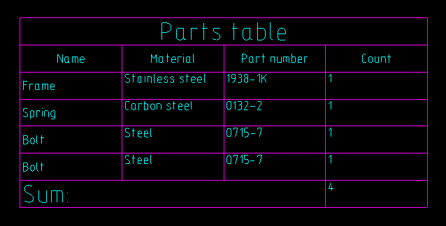
After the table is created, you can modify its structure: add, delete, move or copy rows and columns. For example, let’s add one extra record for a “Bolt” component, then move the “Count” column to the last position and delete the “Index” column:
|
1 2 3 4 5 |
Table1.Rows.CopyRange(4, 5, 1, true); Table1.Columns.Move(2,5); Table1.Columns.Delete(0); |
Then add a row for a total number of components. For counting, the embedded “Summ” expression can be used:
|
1 2 3 4 5 6 7 8 9 10 |
Table1.Rows.AddRange(Table1.Rows.Count, 1); System.Drawing.Rectangle rect2 = new System.Drawing.Rectangle(0, Table1.Rows.Count - 1, Table1.Columns.Count - 2, 0); Table1.Merge(rect2); Table1[Table1.Rows.Count - 1, 0].TextHeight = 5; Table1[Table1.Rows.Count - 1, 0].Value = "Total:"; String SummStartCell = Table1[2, Table1.Columns.Count - 1].AddressOfCell(); String SummEndCell = Table1[Table1.Rows.Count - 2, Table1.Columns.Count - 1].AddressOfCell(); Table1[Table1.Rows.Count - 1, Table1.Columns.Count - 1].ValueFormula = "=summ(" + SummStartCell + ":" + SummEndCell + ")"; |
For summing up the numeric data from the cell region to the result cell, the string representation of the expression has been used. In the table editor the cell will appear as follows:
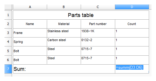
The editor can be launched programmatically using the OnEdit() method from the McTable object.
Note, that we set the numeric format for the “Count” column’s cells instead of the default Auto format, which identifies data type automatically.
Adding tables to the drawing
The table can be added to the drawing just as other entities, using one of the following methods:
Table.DbEntity.AddToCurrentDocument();— adds the table entity to the drawing. The upper left corner of the table is placed at the drawing origin.Table.PlaceObject();— inserts the table interactively, the insertion point is specified by user. Calling the method without arguments or withMcEntity.PlaceFlags.Normalas a parameter value launches the table editor before inserting.
The following allows the table to be added into the drawing in the interactive mode without using the table editor:
|
1 2 3 |
Table1.PlaceObject(McEntity.PlaceFlags.Silent); |
Using blocks and subtables in cells contents
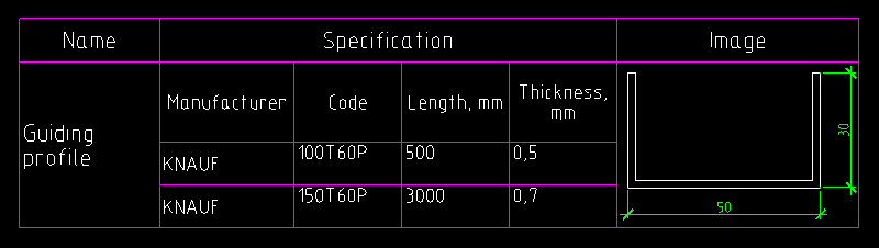
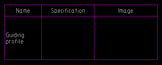
In addition to text and numeric data you can insert blocks and other tables into a table’s cells. Let’s look at how this works with a sample table that describes a metal structural profile. The first column contains the shape type, the second column: its specification, and the third column: its graphical representation:
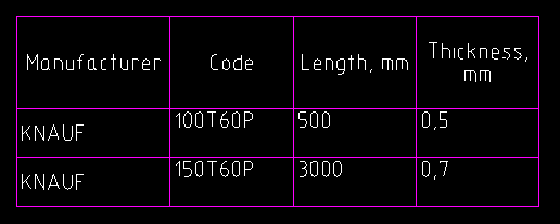
The specification for the profile is represented by the following table:
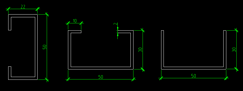
Images of different shape types are represented by separate blocks stored in an external .dwg file:
Let’s discuss how we can add a profile’s specification and image to the main table.
Inserting subtables
To insert subtables, the following method is used:
McTable.InsertSubtable(ref McTable inTable, int row, int col, InsertionModeEnum mode);
inTable— the table to insert,row, col— row and column indexes of the cell to which the subtable will be inserted,mode— the insertion mode.
The subtable can be inserted in the following modes:
InSingleCell— the table will be inserted into the specified cell. The structure of the resulting table will be adjusted in order to fit the inserted table.CellByCell— the table will be inserted cell-by-cell starting from the upper left cell. The resulting table will contain only overlapping cells from both tables.Over— the table will be inserted over the main table. Neither of the tables’ structure will be changed.
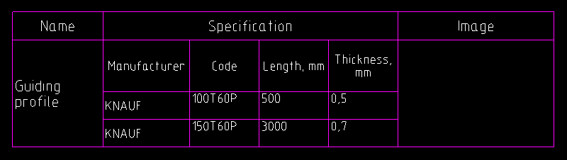
The following code inserts the specification table to a separate cell of the main table:
|
1 2 3 |
Table1.InsertSubtable(ProfileTable1, 1, 1, InsertionModeEnum.InSingleCell); |
Using blocks as cell content
For inserting blocks into table cells, the EmbedBlock() method of a Cell object is used. This method enables embedding of a block in a separate cell using block ID, block name, or block name and name of an external file that contains the block:
bool EmbedBlock(int row, int col, McObjectId Id);
bool EmbedBlock(int row, int col, ref String name);
bool EmbedBlock(int row, int col, ref String name, ref String fileName);
The following code inserts the block of the shape’s image from the external file:
|
1 2 3 4 |
Table1[1, 0].Value = "Guiding profile"; Table1[1, 2].EmbedBlock("Profile_03", "C:\\Profiles.dwg"); |
Extracting properties from entities to a table
Another useful feature of the MultiCAD.NET API is attaching entities to the table. Since the object is attached, you are able to extract its properties to a cell using special expressions. The following example demonstrates how to attach a closed polyline to the table and use its area property as a value of the cell (0,0):
|
1 2 3 4 |
String object = Table1.AttachObject(polyline.ID); Table1[0, 0].ValueFormula = object + ".\"Geometry.Area\""; |
Attaching objects allows you to track changes dynamically. Changing properties of the attached object changes the contents of corresponding table cells.
Pingback: Tables in MultiCAD.NET. Part 3: Saving and loading table from an external file | nanoCAD API Blog