
One of the key disadvantages of classical .NET APIs in .dwg-compatible CAD programs is that it is impossible to create custom entities in .NET. Custom entities must be created in C++ with managed C++/CLI wrappers to be usable in .NET .
Our MultiCAD .NET technology provides the ability to create custom entities within the bounds of managed code. In addition to not requiring intermediate C++ objects, MultiCAD .NET uses standard .NET mechanisms, so there is no need to manually serialize objects, create COM objects, or perform other overhead chores that are typical with CAD programming.
The CustomObjects sample application, delivered with the SDK, provides a good example of how MultiCAD .NET works. This application creates a custom entity, TextInBox, that draws a framed text string:
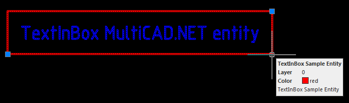
TextInBox sample entity
A drawing containing this custom entity can be opened by any .dwg-compatible CAD program. The entity can be modified by loading an assembly, containing the entity’s code. The same assembly can be correctly loaded to all supported CAD platforms without recompiling.
MultiCAD .NET technology runs natively in nanoCAD, and works in AutoCAD (and other compatible CAD programs) through an Object Enabler extension module, which can be downloaded in the nanoCAD Developers’ Club.
Defining a custom entity class
To create a new custom entity type, it’s necessary to define a new class, derived from McCustomBase (the base class for all custom entities.) Two attributes are required for the defined class:
[CustomEntity]attribute with specified class type, its GUID, the name that will be used for all such entities in the drawing’s database and the local name,[Serializable]attribute allows for using the standard serialization mechanism from .NET Framework.
The following code defines the TextInBox custom entity class:
|
1 2 3 4 5 6 7 8 9 10 11 12 13 |
[CustomEntity(typeof(TextInBox), "1C925FA1-842B-49CD-924F-4ABF9717DB62", "TextInBox", "TextInBox Sample Entity")] [Serializable] public class TextInBox : McCustomBase { // First and second vertices of the box private Point3d _pnt1 = new Point3d(50, 50, 0); private Point3d _pnt2 = new Point3d(150, 100, 0); // Text inside the box private String _text = "Text field"; } |
The methods from the base McCustomBase class for drawing entity geometry, adding into the database, selecting, and modifying the object are overridden by the TextInBox class.
Drawing geometry
The OnDraw() method is used for drawing the object. This method uses the GeometryBuilder class as a parameter.
|
1 2 3 4 5 6 7 8 9 10 11 12 13 14 15 16 17 18 19 20 21 22 23 24 25 26 27 28 29 |
public override void OnDraw(GeometryBuilder dc) { dc.Clear(); // Set the color to ByObject value dc.Color = McDbEntity.ByObject; // Draw box with choosen coordinates dc.DrawPolyline(new Point3d[] { _pnt1, new Point3d(_pnt1.X, _pnt2.Y, 0), _pnt2, new Point3d(_pnt2.X, _pnt1.Y, 0), _pnt1}); // Set text height dc.TextHeight = 2.5 * DbEntity.Scale; // Set text color dc.Color = Color.Blue; // Draw text at the box center dc.DrawMText(new Point3d((_pnt2.X + _pnt1.X) / 2.0, (_pnt2.Y + _pnt1.Y) / 2.0, 0), Vector3d.XAxis, Text, HorizTextAlign.Center, VertTextAlign.Center); } |
Adding an entity into a drawing, with interactive coordinate input
The PlaceObject() method is used for adding custom entities into the drawing. Apart from its primary purpose, this method is also used for interactive coordinate input. In the MultiCAD API, interactive input is implemented in the InputJig class, which contains all essential functionality:
public InputResult GetPoint(string prompt)— gets a point on the drawing from user input. Thepromptparameter is used to show a prompt.public void ExcludeObject(McObjectId ObjectId)— excludes a specified object from snap. (This can be used to prevent an object from snapping itself.)public EventHandler MouseMove— the mouse movement event handler, used for monitoring mouse motion and interactive object redrawing.
This code implements the PlaceObject method:
|
1 2 3 4 5 6 7 8 9 10 11 12 13 14 15 16 17 18 19 20 21 22 23 24 25 26 27 28 29 30 31 32 |
public override hresult PlaceObject(PlaceFlags lInsertType) { InputJig jig = new InputJig(); // Get the first box point from the jig InputResult res = jig.GetPoint("Select first point:"); if (res.Result != InputResult.ResultCode.Normal) return hresult.e_Fail; _pnt1 = res.Point; // Add the object to the database DbEntity.AddToCurrentDocument(); // Exclude the object from snap points jig.ExcludeObject(ID); // Monitoring mouse motion and interactive entity redrawing jig.MouseMove = (s, a) => {TryModify(); _pnt2 = a.Point; DbEntity.Update(); }; // Get the second box point from the jig res = jig.GetPoint("Select second point:"); if (res.Result != InputResult.ResultCode.Normal) { DbEntity.Erase(); return hresult.e_Fail; } _pnt2 = res.Point; return hresult.s_Ok; } |
Editing and Modifying Object
To add object-modifying and text-editing features to the TextInBox class, the following methods from the base class are overridden:
public virtual List OnGetGripPoints()— get the list of object’s grip points (the marked points on the object that are used for transforming the object.)public virtual void OnMoveGripPoints(List indexes, Vector3d offset, bool isStretch)— the grip points moving event handler.public virtual void OnTransform(Matrix3d tfm)— defines object transformations.public virtual hresult OnEdit(Point3d pnt, EditFlags lInsertType)— the object editing event handler.
This code sets the grip points to the box corner points input by the user:
|
1 2 3 4 5 6 7 8 9 |
public override List OnGetGripPoints() { List arr = new List(); arr.Add(_pnt1); arr.Add(_pnt2); return arr; } |
When the custom entity is selected, the grip points are shown:
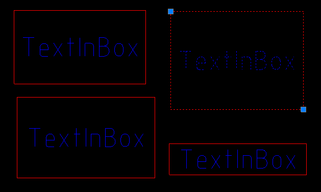
This event handler code allows the grip points to be moved by dragging:
|
1 2 3 4 5 6 7 8 9 10 11 12 13 14 15 16 17 18 19 20 |
public override void OnMoveGripPoints(List indexes, Vector3d offset, bool isStretch) { if (!TryModify()) return; if (indexes.Count == 2) { _pnt1 += offset; _pnt2 += offset; } else if (indexes.Count == 1) { if (indexes[0] == 0) _pnt1 += offset; else _pnt2 += offset; } } |
The indexes parameter is a list of grip points indexes, and offset is a grip points displacement vector.
The OnTransform() method calculates the new positions of both corner points after transformations:
|
1 2 3 4 5 6 7 8 9 10 11 |
public override void OnTransform(Matrix3d tfm) { //Save Undo state and set the object status to "Changed" if (!TryModify()) return; _pnt1 = _pnt1.TransformBy(tfm); _pnt2 = _pnt2.TransformBy(tfm); } |
And finally, a text string editing method is required. Editing can be initiated by double-clicking on the entity, or by choosing the proper item from the context menu. Once the edit command is called, the form with text field appears to enable setting a new value for the text string:
|
1 2 3 4 5 6 7 8 9 10 |
public override hresult OnEdit(Point3d pnt, EditFlags lInsertType) { TextInBox_Form frm = new TextInBox_Form(); frm.textBox1.Text = Text; frm.ShowDialog(); Text = frm.textBox1.Text; return hresult.s_Ok; } |

TextInBox edit form
Adding Object Properties to the Property Inspector
The MultiCAD .NET API provides the ability to add the properties of a custom entity to a property inspector regardless of the platform used for opening the .dwg file, be it AutoCAD or nanoCAD. This can be done by adding the following attributes to the appropriate public property:
DisplayNameAttribute— defines the property name for displaying in the inspector;DescriptionAttribute— property description;CategoryAttribute— defines the name of the category for the property.
Use this feature to add the Text property to the properties palette:
|
1 2 3 4 5 6 7 8 9 10 11 12 13 14 15 16 17 18 19 20 21 |
[DisplayName("Text label")] [Description("Label description")] [Category("Text object")] public String Text { get { return _text; } set { //Save Undo state and set the object status to "Changed" if (!TryModify()) return; // Set new text value _text = value; } } |
This will display the contents of the entity’s text component in the property inspector:
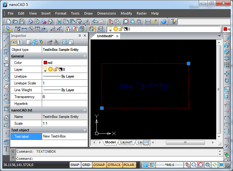
Text property shown in the inspector
In this example, we have created a custom entity that can be added to the .dwg drawing and standard modifications for CAD users. This set of entities’ features can be extended as well. In later articles we’ll talk about creating entity versions by adding new fields and by renaming (removing) existing fields, and discuss the specifics of entity versioning in MultiCAD.NET API.
Pingback: Selecting and editing custom entities in MultiCAD.NET | nanoCAD API Blog
Pingback: MultiCAD.NET API: Saving non-graphical data in .dwg drawings | nanoCAD API Blog