Monthly Archives: April 2014

Tables in MultiCAD.NET. Part 3: Saving and loading table from an external file

Tables_21_en

The previous post about tables in MultiCAD.NET described how to create, modify and format tables with different data types and mentioned using table templates. In this post we will talk about templates and look more closely at the API that allows you to save a table to an external file as a template and then load it to the drawing to create type tables. Also the post will describe the table data exchange process between a MultiCAD.NET application and Microsoft Excel.
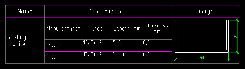
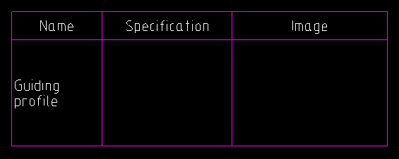
Example table

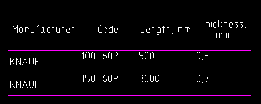
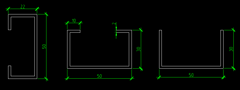
Let’s assume that the example table describes different types of mounting profiles (C-studs, U-channels etc.) and contains the following data: name, code, thickness, function.

Tables_12_en

Example table

We showed how to create and format tables in the previous post. Here, we’ll discuss how to save this table to an external file so that we can use it later as a template.

Saving table as a template

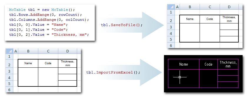
To save a table to a separate file, the McTable.SaveToFile() method is used. The table can be saved to a file of one of the following formats:

  • .dat files,
  • tabbed text (.txt),
  • comma-separated text,
  • XML,
  • Microsoft Excel (.xls),
  • OpenOffice.org (.ods).

The table to be saved can be picked from the drawing. The following command allows user to pick a table and save it to a file of the available formats:

Loading table from a file

To load a table from an external file, use the McTable.LoadFromFile() method. As well as for SaveToFile(), the file name can be specified explicitly or chosen from the dialog. The following file formats are supported for loading:

  • table .tbl, .dat files,
  • text (.txt, .csv, .xml),
  • Microsoft Access(.mdb, .accdb),
  • Microsoft Excel (.xls, .xlsx),
  • OpenOffice.org (.ods),
  • StarOffice (.sxc)

The following command adds a table from the user selected file to the drawing:

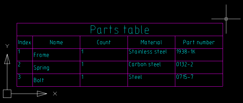
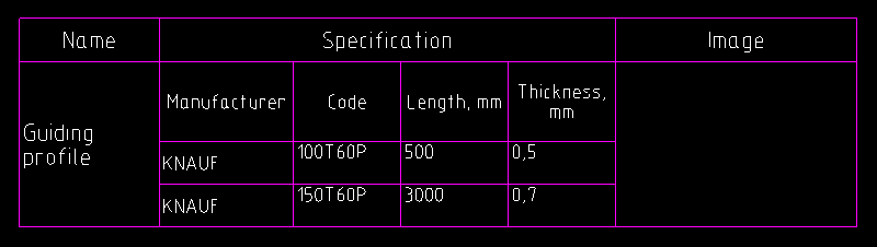
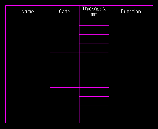
Now the saved table can be used as a template for adding type tables to the drawing:

Tables_13_en

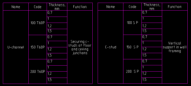
Type tables based on the template table

Exchanging data with Excel

In addition to saving tables to files, MultiCAD.NET has the ability to quickly exchange data with Microsoft Excel sheets.

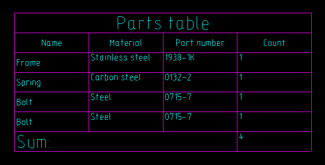
When the ExportToExcel() method is called, the table data is copied to a newly created and opened Excel book, keeping the cells format the same.
The following command lets the user select a table in the drawing and export it to an Excel sheet:

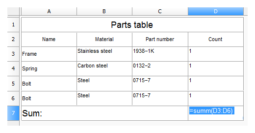
Also MultiCAD.NET supports importing table data from Excel. To import a selected cell range from the opened Excel sheet, use the ImportFromExcel() method:

This post concludes our review of the basic features of the tables API in MultiCAD.NET. This was definitely not the entire list of the abilities provided by the API, so if you have any questions or suggestions regarding this functionality please feel free to write comments. The tables feature list is currently being enhanced and we’ll be happy to get suggestions for more subjects to discuss in future posts.

Tables in MultiCAD.NET. Part 2: Creating and modifying

Tables_11_en

In the previous post we saw an example of using the MultiCAD.NET API for creating an automatic report with extracted properties from select drawing objects. We’ve purposely disturbed the chronological order. In today’s post we will create and modify a simple table. Then we’ll fill the table with text and numeric data, using expressions. Finally, we’ll switch over to adding blocks and subtables as cell content and conclude by attaching objects to the table to practice using their properties as the table’s dynamic contents.

Creating and formatting tables

In the MultiCAD.NET API, table entities are represented by the McTable class from the Multicad.Symbols.Tables namespace. The following code creates an empty table and  adds two rows and three columns starting at 0 index:

With the same method, you can add row and column ranges at specific positions.

Let’s add the content for the newly created table and define cell formating. The table will contain a property list of construction elements: index, name, part number, material and count. For the count column we will use a numeric cell format and the other cells will contain text data.

Tables_01_en

One of the advantages of the MultiCAD.NET table API is an ability to use different fit modes for oversized text. With the HorzFits property you can choose the following horizontal fitting options if text width exceeds cell bounds:

  • HorizontalFitsEnum.None — leave as is,
  • HorizontalFitsEnum.Shrink — adjust width factor (default mode),
  • HorizontalFitsEnum.Wrap — word wrap.

The VertFits property defines the text fitting if text height exceeds cell bounds:

  • VerticalFitsEnum.None — leave as is,
  • VerticalFitsEnum.Shrink — shrink text height (default mode),
  • VerticalFitsEnum.Expand — expand row height,
  • VerticalFitsEnum.AddRows — occupy extra rows.

After the table is created, you can modify its structure: add, delete, move or copy rows and columns. For example, let’s add one extra record for a “Bolt” component, then move the “Count” column to the last position and delete the “Index” column:

Then add a row for a total number of components. For counting, the embedded “Summ” expression can be used:

Tables_03_en

For summing up the numeric data from the cell region to the result cell, the string representation of the expression has been used. In the table editor the cell will appear as follows:

Tables_04_en

The editor can be launched programmatically using the OnEdit() method from the McTable object.

Note, that we set the numeric format for the “Count” column’s cells instead of the default Auto format, which  identifies data type automatically.

Adding tables to the drawing

The table can be added to the drawing just as other entities, using one of the following methods:

  • Table.DbEntity.AddToCurrentDocument(); — adds the table entity to the drawing. The upper left corner of the table is placed at the drawing origin.
  • Table.PlaceObject(); — inserts the table interactively, the insertion point is specified by user. Calling the method without arguments or with McEntity.PlaceFlags.Normal as a parameter value launches the table editor before inserting.

The following allows the table to be added into the drawing in the interactive mode without using the table editor:

Using blocks and subtables in cells contents

In addition to text and numeric data you can insert blocks and other tables into a table’s cells. Let’s look at how this works with a sample table that describes a metal structural profile. The first column contains the shape type, the second column: its specification, and the third column: its graphical representation:

Tables_06_1_en

The specification for the profile is represented by the following table:

Tables_05_en

Images of different shape types are represented by separate blocks stored in an external .dwg file:

Tables_06_en

Let’s discuss how we can add a profile’s specification and image to the main table.

Inserting subtables

To insert subtables, the following method is used:

McTable.InsertSubtable(ref McTable inTable, int row, int col, InsertionModeEnum mode);

  • inTable — the table to insert,
  • row, col — row and column indexes of the cell to which the subtable will be inserted,
  • mode — the insertion mode.

The subtable can be inserted in the following modes:

  • InSingleCell — the table will be inserted into the specified cell. The structure of the resulting table will be adjusted in order to fit the inserted table.
  • CellByCell — the table will be inserted cell-by-cell starting from the upper left cell. The resulting table will contain only overlapping cells from both tables.
  • Over — the table will be inserted over the main table. Neither of the  tables’ structure will be changed.

The following code inserts the specification table to a separate cell of the main table:

Tables_10_en

Using blocks as cell content

For inserting blocks into table cells, the EmbedBlock() method of a Cell object is used. This method enables embedding of a block in a separate cell using block ID, block name, or block name and name of an external file that contains the block:

bool EmbedBlock(int row, int col, McObjectId Id);
bool EmbedBlock(int row, int col, ref String name);
bool EmbedBlock(int row, int col, ref String name, ref String fileName);

The following code inserts the block of the shape’s image from the external file:

Tables_11_en

Extracting properties from entities to a table

Another useful feature of the MultiCAD.NET API is attaching entities to the table. Since the object is attached, you are able to extract its properties to a cell using special expressions. The following example demonstrates how to attach a closed polyline to the table and use its area property as a value of the cell (0,0):

Attaching objects allows you to track changes dynamically. Changing properties of the attached object changes the contents of corresponding table cells.