Extension of the menu functionality in nanoCAD 8.5: macros and LISP expressions

m00

The nanoCAD menu files have the .cfg extension and a structure different from the menu structure (*.mnu*.cui*.cuix) of other CADs. In the 8.5 version, the support of macros has been added that can include several commands and parameters, as well as LISP expressions.

Complex macro in the menu

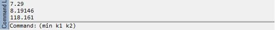
As an example, let’s write a single-item drop-down menu MyTest.cfg (with the Notepad text editor) that creates a round hole of radius 500 in the center point 700,600 in a drawing with the CIRCLE command. The dialog in the command line of such macro is shown in Fig. 1. The user must click on the menu item only one time without the need to enter any other data.

m01

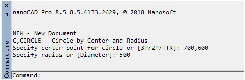
Fig. 1. The result of executing a complex menu macro

To create such a menu, you must fill in the menu and commands sections in the MyTest.cfg file:

[\]
[\menu]
[\menu\MyTest]
Name=sMyTest

[\menu\MyTest\MenuItem500]
Name=sHole_R500
Intername=sMHole500

[\configman]
[\configman\commands]

[\configman\commands\MHole500]
Weight=i30
CmdType=i1
Intername=sMHole500
LocalName=sHole_R500
DispName=sInsert_a_hole_R500
StatusText=sAdd a hole R500
ToolTipText=sHole R500
Keyword=s_.CIRCLE;700,600;500;
IsUserCommand=f1

This file includes the description of the new MHole500 command with such macro (the s character before is a special one):

_.CIRCLE;700,600;500;

This macro includes the CIRCLE command and two parameters: 700,600 (the center point coordinates) and 500 (the radius value), which are separated by a semicolon (the equivalent of pressing Enter when running on the command line).
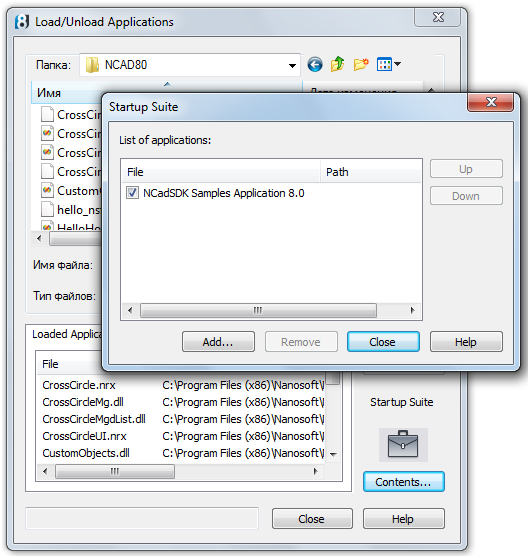
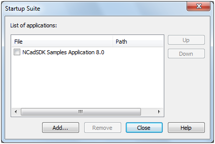
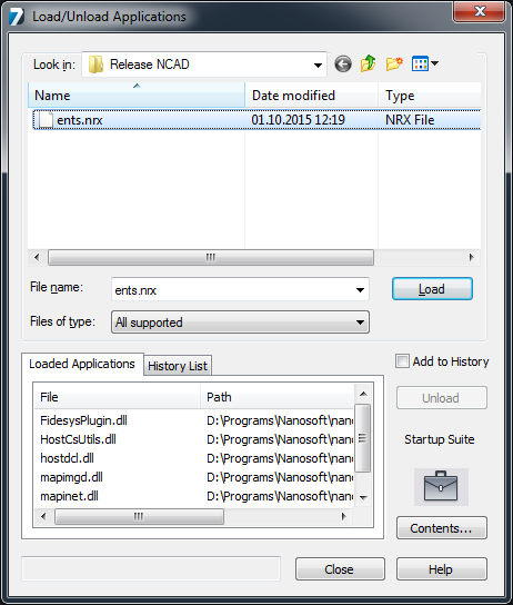
To simplify loading this menu, let us use the testcfg.package packet file, specifying its name in the startup suite. To do this, select the menu item Tools > Application > Load application, and in the Load/Unload Applications, click on the Contents button under the briefcase image (Fig. 2).

m02

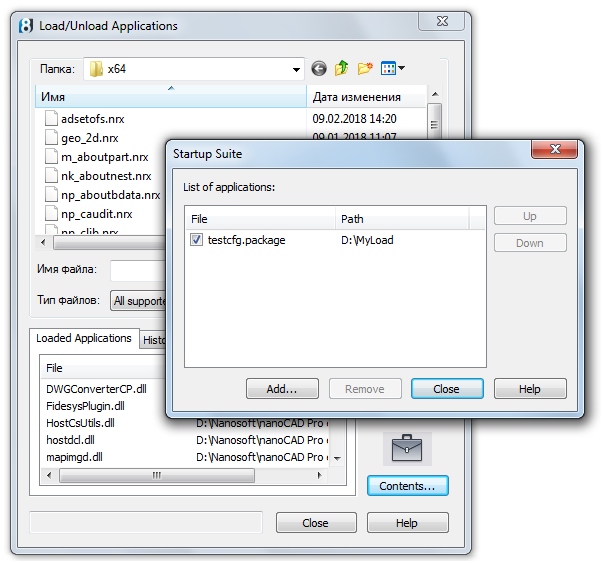
Fig. 2. Autoloading testcfg.package using the suite

In the Startup Suite  child window, using the Add button, add the testcfg.package file to the list of autoloaded files. Save this file before in the D:\MyLoad folder side by side with MyTest.cfg side by side with MyTest,cfg. In the testcfg.package file, which is a XML-file in UTF-8 encoding (it is important!), write the following:

<?xml version=”1.0″ encoding=”utf-8″ ?>
<ApplicationPackage
xmlns=”hostModulePackage/v01″
Name=”Tests”
>
<Components>
<ConfigEntry
FileName=”MyTest.cfg”
FileType=”CFG”
/>
</Components>
</ApplicationPackage>

Here, in the ConfigEntry tag, specify the data about the CFG file, which must be loaded immediately after loading the main nanoCAD core (there must be several tags, if you want to load several CFG files). For more details about .package files, see the article Customizing the User Interface When Installing Apps For nanoCAD Plus 8.5“.

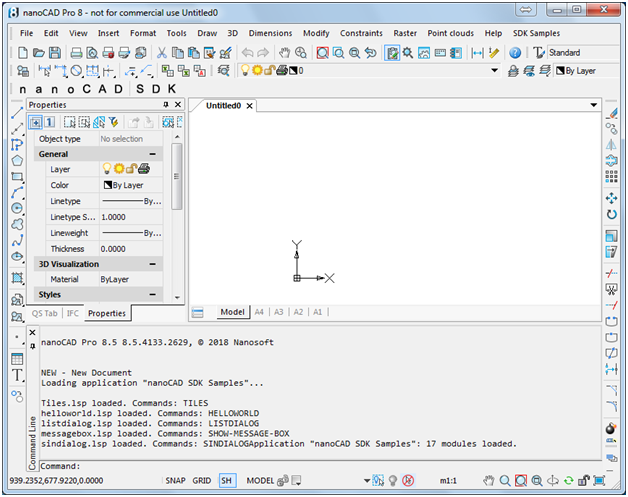
After closing the Startup Suite and Load/Unload Applications and restarting nanoCAD, you will see our MyTest menu in the menu bar (Fig. 3):

m03

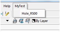
Fig. 3. MyTest in the menu bar

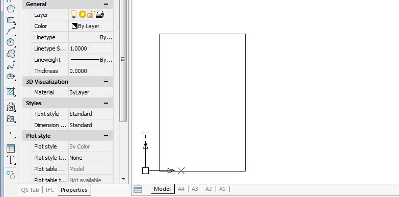
The dropdown menu includes one item which creates a circle with a fixed radius and a fixed center (Fig. 4):

m04

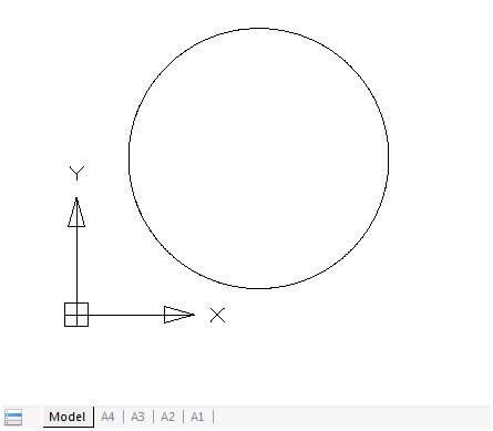
Fig. 4. The circle drawn

The macro we wrote is a complex one (it includes three parts). But it implements a very simple option. Let us expand the task: allow the user himself or herself specify the center point.

Pause in the menu

The 8.5 version, the function of pause processing in macros has been added. To illustrate this, let us copy the MyTest.cfg file in MyTest1.cfg; rename the MHole500 command to M1Hole500, and change the macro text in the Keyword parameter:

[\configman\commands\M1Hole500]
weight=i30
CmdType=i1
Intername=sM1Hole500
LocalName=sHole_R500
DispName=sInsert_a_hole_R500
StatusText=sAdd a hole R500
ToolTipText=sHole R500
Keyword=s_.CIRCLE;\500;
IsUserCommand=f1

The macro is as follows:

_.CIRCLE;\500;

As compared with the macro in the previous example, there is no center, but there is back slash (\). This is a pause signal for user input (there, the CIRCLE command requests the center point).
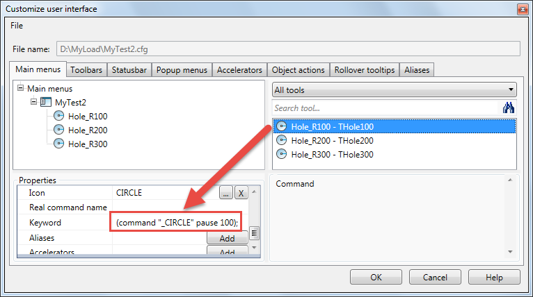
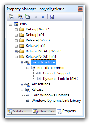
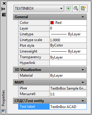
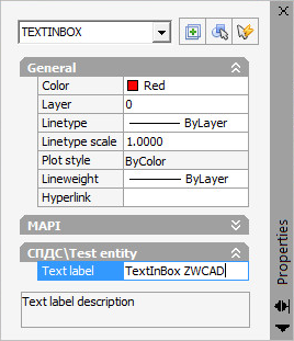
Fig. 5 shows how our macro looks like if we load the MyTest1.cfg file into the interface editor using the INTERFACE command (or using the menu item Tools > Customize> Interface) and select the MyTest1.cfg file using File > Open.

m05

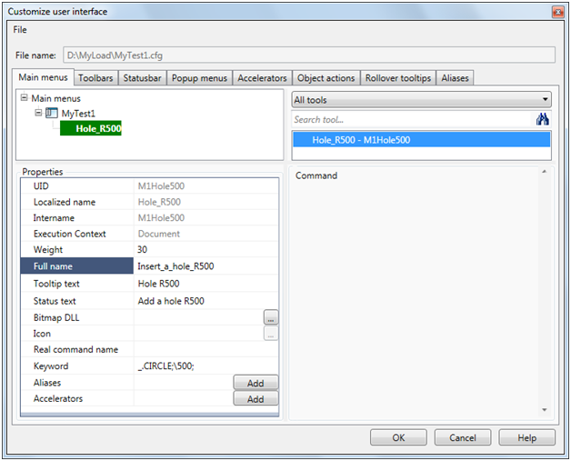
Fig. 5. Displaying a macro with a pause symbol in the interface editor

In the Properties pane, the macro text is shown in the Keyword parameter.

Important note. When you save menu files in the interface editor, they replace the main menu of the nanoCAD platform. To return to the previous main menu, use the SETCONFIG command or edit manually the file c:\Users\user\AppData\Roaming\Nanosoft\nanoCAD [x64] Pro Int 8.5\Config\cfg.ini.

Let us edit the testcfg.package file (you can add the MyTest1.cfg menu in it). Here is an exemplary result of running the macro (Fig. 6):

m06

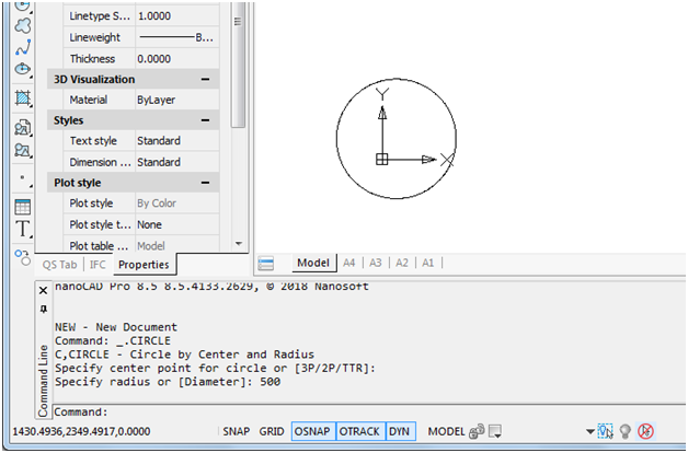
Fig. 6. Running a macro including a pause character

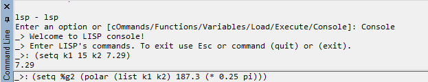
LISP expressions in the menu

Processing LISP expressions in the command line is another step forward in nanoCAD 8.5. At the same time, it is possible to include LISP expressions in the macro menu.
For example, let us write another variant of the menu (MyTest2.cfg), but already including three items that implement creating round holes in the drawing using the CIRCLE command. The commands must run through LISP expressions. The menu items will differ only in their radius values (100, 200, and 300). There, the hole center point will be requested using a pause (the PAUSE LISP symbol). At the same time, let us complicate the menu items adding a standard icon of the CIRCLE command. The system icons are in the newbtns.dll file which is part of the nanoCAD software. The icon name is the same as the command name.
[\]
[\menu]
[\menu\MyTest2]
Name=sMyTest2
[\menu\MyTest2\MenuItem100]
Name=sHole_R100
Intername=sTHole100

[\menu\MyTest2\MenuItem200]
Name=sHole_R200
Intername=sTHole200

[\menu\MyTest2\MenuItem300]
Name=sHole_R300
Intername=sTHole300

[\configman]
[\configman\commands]

[\configman\commands\THole100]
Weight=i30
CmdType=i1
Intername=sTHole100
LocalName=sHole_R100
DispName=sInsert_a_hole_R100
StatusText=sAdd a hole R100
ToolTipText=sHole R100
BitmapDll=snewbtns.dll
Icon=sCIRCLE
Keyword=s(command “_.CIRCLE” pause 100);
IsUserCommand=f1

[\configman\commands\THole200]
Weight=i30
CmdType=i1
Intername=sTHole200
LocalName=sHole_R200
DispName=sInsert_a_hole_R200
StatusText=sAdd a hole R200
ToolTipText=sHole R200
BitmapDll=snewbtns.dll
Icon=sCIRCLE
Keyword=s(command “_.CIRCLE” pause 200);
IsUserCommand=f1

[\configman\commands\THole300]
Weight=i30
CmdType=i1
Intername=sTHole300
LocalName=sHole_R300
DispName=sInsert_a_hole_R300
StatusText=sAdd a hole R300
ToolTipText=sHole R300
BitmapDll=snewbtns.dll
Icon=sCIRCLE
Keyword=s(command “_.CIRCLE” pause 300);
IsUserCommand=f1

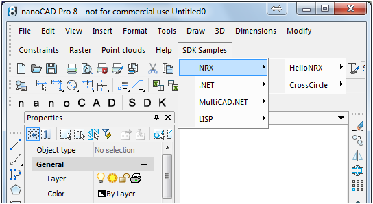
This file includes the description of three commands (THole100, THole200, THole300), that operate by running LISP expressions with a command function. See how the macros with a LISP expression looks like in the interface editor (in the figure, at the beginning of the article, the menu MyTest2.cfg is shown).

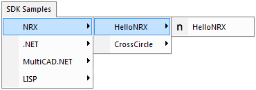
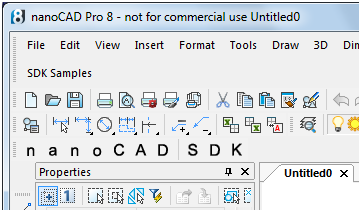
After completing the above operations with the startup suite and restarting nanoCAD, we will see our menu MyTest2 in the menu bar (Fig. 7):

m07

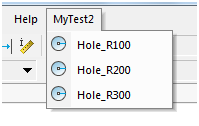
Fig. 7. MyTest2 with three menu items

The drop-down menu includes three items that create circles with three radiuses (Fig. 8):

m08

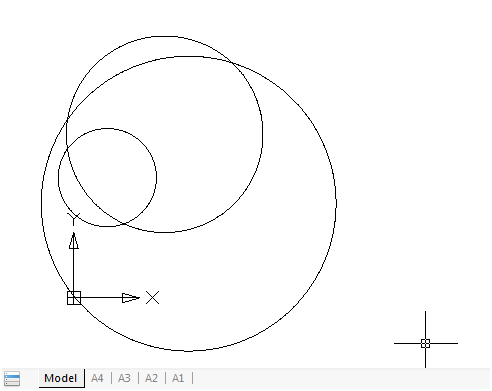
Fig. 8. The result of running three menu items

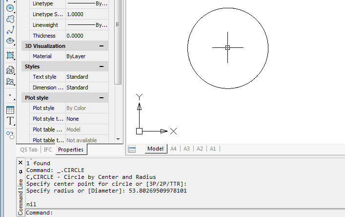
Transparent commands

In the nanoCAD system, some commands (such as ZOOM or PAN) can be run in a transparent mode, without interfering with other commands previously started. The 8.5 version implements running commands in a transparent mode from the command line with an apostrophe added before their names, by analogy with other CAD systems (Fig. 9):

m09

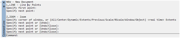
Fig. 9. A transparent ‘ZOOM command entered in the command line

In this example, when running the LINE command, the ‘ZOOM command was run in a transparent mode with the E parameter (Zoom Extents), whereupon the control returns successfully back to the LINE command.
It is possible to include transparent commands in the menu macro, for example:

Keyword=s_.CIRCLE;’_.ZOOM;_E;\400;

The *.cuix converter to *.cfg

When exporting user menus from AutoCAD to nanoCAD, the CuixConverter.exe utility function can be used, ftp.nanocad.ru/habr/CUIX85/CuixConverter85.zip.

It reads a CUIX file and creates a corresponding CFG file. The syntax for using the converter (on the example of my.cuix):

CuixConverter.exe [<path>\]my.cuix

<path> may be absolute or relative (according to Windows rules). If the path is not specified, the file must be stored in the current folder. As a result of running the utility function, the my.cuix.cfg file with the conversion results will be created in the same <path> folder. This will save you from the painstaking work on writing CFG files manually or using the Tools > Customize > Interface command.
To run the converter, use the Windows command line console. It can be opened by typing cmd in the Windows run line. Here is an example of working with the MyMenu.cuix file, which is stored in the same folder as the converter files: *.exe*.dll (Fig. 10):

m10

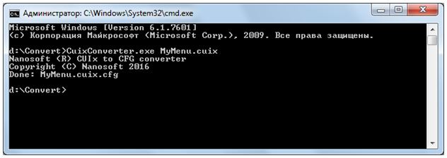
Fig. 10. The Windows command line console with the result of running the converter

As a result of successful running, you will see the following message:
Done: MyMenu.cuix.cfg
.

Nikolay Poleshchuk

nanoCAD 8.5 – New LISP Features

LISP support in nanoCAD has been added long ago and was mainly associated with special LSP command allowing to operate LISP console for input expressions and analyzing variables:

r01

Fig. 1. LISP console window

8.5 release is the next important step forward: now you can enter LISP expressions in the command line; besides, PAUSE symbol support has been added. The advancements covered herein have been added into 8.5 release starting from version 8.5.4131.2629, build 4133.

LISP expressions instead of a command

In case there are no other requests Command: prompt will now allow entering LISP expressions. For example:
(min k1 k2),
where k1 and k2 are global variables (Fig. 2):

r02

Fig. 2. LISP expression in the command line

When you press Enter, the system returns the result in the command line. It is also possible executing commands and entering parameters using the command LISP function. For example, let’s take the RECTANGLE command  (Fig. 3):

r03

Fig. 3. An example of a LISP expression for the RECTANGLE command

And we see the on-screen result of the command above:

r04

Fig. 4. The result of the RECTANGLE command

PAUSE symbol in LISP – interact better with possible user input

8.5 version features the support of PAUSE symbol so a command execution can now be interrupted to request user input. Case study: we know the radius of the circle, but not the center point. Here we can simply request it using  the following expression:
(command “_.CIRCLE” PAUSE (sqrt 2894.73))

And we can see the result in Fig. 5:

r05

Fig. 5. Interrupting the CIRCLE command using PAUSE

We’ve launched the CIRCLE command, interrupted it to request the center point coordinates and, after the user input has been received, it was completed using the calculation result of (sqrt 2894.73) as the radius value.
It is possible to repeatedly use PAUSE  in a single  LISP expression, for example:
(command “_.CIRCLE” PAUSE PAUSE)

LISP variables value

Debugging often requires checking the current value of LISP variables. A method of using the exclamation mark to get the current value of the global LISP variable is known from other CAD systems,  for example:
!myvar

8.5 version has a different approach offering eval function for the same. So the following expression will return the value of myvar:
(eval myvar)

eval function operates differently with data of different types; therefore, it is necessary to add quote function for variables storing list values, for example:
(setq lista1 (list 1 (list 2 99)))
(eval lista1) returns an error
(eval (quote lista1)) returns (1 (2 99))

Nikolay Poleshchuk

Customizing the User Interface When Installing Apps for nanoCAD Plus 8.5

SDK samples_01

For many users, installing an application means just adding a new desktop shortcut or a new toolbar button. This article will describe the way to add menus and toolbars for user applications installed on nanoCAD Plus 8.5 or nanoCAD Pro 8.5, and analyze the procedure for creating a shortcut to launch a user application in the nanoCAD environment.
For those who are more interested in trying rather than in reading a description, I will immediately provide a link to the nanoCAD SDK Samples add-in. After installing this application, each start of nanoCAD Plus 8.5 will automatically load samples created in LISP, C++, С#, VB.NET, JScript, and VBScript, and the user interface will be added with a drop-down menu and a toolbar (as in the main screenshot), allowing you to run sample commands.
As a first step, let us present a ready-made application for installing samples supplied with nanoCAD Pro 8.5: NCadSDK Samples Application 8.0, and then we will consider how to include the file of menu description and toolbars there.

SDK samples_02

Samples Installer Overview

The samples installer for nanoCAD is a file in the Windows Installer format named SamplesAppEn<version>.msi. After startup, it builds a list of installed nanoCAD versions that are compatible with the installer, inviting your to select the versions where to install the application and those to be excluded from the installation:

SDK samples_03

SDK samples_04

SDK samples_05

Installation folder: C:\Program Files (x86)\Nanosoft\NCadSDK Samples Application 8.0\NCAD80.
The installed application NCadSDK Samples Application 8.0 is already in the startup suite:

SDK samples_06

Check it if it is still unchecked and rerun nanoCAD.
When nanoCAD 8.5 starts, a message about the application being loaded is displayed in the command line:

SDK samples_07

You can run the loaded commands:

• from the command line
• from the drop-down menu installed with the application:

SDK samples_08

• or using the nanoCAD SDK toolbar where some SDK sample commands are added:

SDK samples_09

What is Installed Using the Installer?

For each nanoCAD version selected during installation, the Installer creates a directory including sample files:

SDK samples_10

For 8.0–8.5 platforms, the full set of samples is installed (NCAD80 folder), whereas for the previous versions of the platform, it installs only scripts (JS, VBS) that do not require recompiling for each platform (the folders are named according to the version number: NC70, etc.). This is not a limitation of the application installation technology: if you compile SDK samples of all previous versions, you can create a unique installer to install the full set of samples on all platforms supported.

SDK samples_11

Application Description File (*.package)

SDK samples_12

In addition to application file, the folder with installed samples includes the package file with .package extension, which contains all the necessary information about nanoCAD user configurations (including applications to load and user menus) and allows for loading the selected configuration immediately after launching nanoCAD.
Let us consider the package file to load add-in modules from the set of samples for nanoCAD. The file text has the following XML structure:

<?xml version=”1.0″ encoding=”utf-8″ ?>

<ApplicationPackage
xmlns=“hostApplicationPackage/v01″
Name=“nanoCAD SDK Samples”
>
<Components>
<ConfigEntry
FileName=“NCADSDK.cfg”
FileType=“CFG”
/>
<ComponentEntry
AppName=“HelloNRX minimal NRX sample”
ModuleName=“HelloNRX.nrx”
ModuleType=“NRX”
/>
<ComponentEntry
AppName=“CrossCircle Object Enabler”
ModuleName=“CrossCircle.nrx”
ModuleType=“NRX”
/>
<ComponentEntry
AppName=“CrossCircle Commands”
ModuleName=“CrossCircleUI.nrx”
ModuleType=“NRX”
/>
<ComponentEntry
AppName=“CrossCircle Managed Wrapper”
ModuleName=“CrossCircleMg.dll”
ModuleType=“NRX”
/>
<ComponentEntry
AppName=“CrossCircle Managed Commands”
ModuleName=“CrossCircleMgdList.dll”
ModuleType=“MGD”
/>
<ComponentEntry
AppName=“HelloHost .NET Sample”
ModuleName=“HelloHost.dll”
ModuleType=“MGD”
/>
<ComponentEntry
AppName=“HelloHost VB.NET Sample”
ModuleName=“HelloHostVB.dll”
ModuleType=“MGD”
/>
<ComponentEntry
AppName=“MultiCAD Objects”
ModuleName=“McsObjects.dll”
ModuleType=“MultiCAD”
/>
<ComponentEntry
AppName=“MultiCAD Symbols”
ModuleName=“Symbols.dll”
ModuleType=“MultiCAD”
/>
<ComponentEntry
AppName=“MultiCAD .NET Symbols”
ModuleName=“SymbolsMgd.dll”
ModuleType=“MGD”
/>
<ComponentEntry
AppName=“MultiCAD .NET CustomObjects”
ModuleName=“CustomObjects.dll”
ModuleType=“MGD”
/>
<ComponentEntry
AppName=“NSF Commands”
ModuleName=“hello_nsf.nsf”
ModuleType=“NSF”
/>
<ComponentEntry
AppName=“Tiles LISP Sample”
ModuleName=“Tiles.lsp”
ModuleType=“LISP”
/>
<ComponentEntry
AppName=“Hello World DCL Sample”
ModuleName=“helloworld.lsp”
ModuleType=“LISP”
/>
<ComponentEntry
AppName=“ListDialog DCL Sample”
ModuleName=“listdialog.lsp”
ModuleType=“LISP”
/>
<ComponentEntry
AppName=“MessageBox DCL Sample”
ModuleName=“messagebox.lsp”
ModuleType=“LISP”
/>
<ComponentEntry
AppName=“SinDialog DCL Sample”
ModuleName=“sindialog.lsp”
ModuleType=“LISP”
/>
</Components>
</ApplicationPackage>

The elements that are used for package description are:
• ApplicationPackage
• Components
• ConfigEntry
• ComponentEntry

The main element ApplicationPackage includes the Name attribute to define the application name that is displayed in the command line after startup.

The Components element describes the package components: the loaded application module – the ComponentEntry elements, as well as the application configuration file with a menu – ConfigEntry.

ComponentEntry includes the following attributes: AppName with the application name, ModuleName with the executable module name, ModuleType with the module type. The following module types are allowed:

• LISP
• MGD
• MultiCAD
• NRX
• NSF

Command Line Parameters, Creating a Shortcut

NCadSDK Samples Application 8.0 distribution kit adds the application in the startup suite, and it is loaded every time the platform is started. Let’s consider a case when there is no need to automatically load the application, but it should be loaded when launching nanoCAD using a special shortcut on the Windows desktop.

1. Disable add-in startup:

SDK samples_13

2. Create a shortcut for “C:\Program Files (x86)\Nanosoft\nanoCAD Pro en 8.5\nCad.exe” (we assume that we have installed nanoCAD Pro en 8.5 on the C disk, in the Program Files (x86) folder), name it nanoCAD Pro en 8.5 with SDK samples.lnk.

3. Add parameters to the command line:

a. -r — Name of the startup configuration (NCADSamples),
b. -p — Name of the profile (by default, it repeats the name of the startup configuration),
c. -g — path to the loaded application; it may be specified several times.

At the first startup, a profile will be created using the new shortcut, the name of which has been specified in the shortcut command line:

SDK samples_14

Do not confuse the notion of startup configuration and that of the profile:

• The startup configuration includes the information about the main and additional file of user interface (*.cfg) that have been loaded, as well as a link to the current profile. It is designed to create independent configurations (shortcuts) in which applications are run.
• The profile includes the software settings. Various startup configurations can both refer to different, independent profiles and use the same settings, referring to the same profile.

Conclusion

The source code of the nanoCAD sample installer is included in the SDK. If you want to build the installer yourself, you will need the WiX Toolset version 3.8. A sample .cfg file is also included in SDK.

Tags:
• API
• nanocad
• CAD
• lisp

MultiCAD.NET API: Inserting blocks with block attributes

In this post we will talk about inserting blocks using MultiCAD.NET API – one of the most frequently asked questions on our forum.

Let us assume there is a drawing that has block definitions for inserting water supply elements, for example, the blocks that represent valves of different types.

01

Each block definition contains two attributes for providing some extra information about elements.

  • NAME – the element’s name (for example, “Ball”),
  • LABEL – the element’s label (for example, “PC585-70”).

To represent block inserts in the drawing, MiltiCAD.NET provides the McBlockRef class. All you need to do is to create an insert object and assign the name of the block to the BlockName field.

In MultiCAD.NET, block attributes are stored as common object properties. Therefore in order to insert a block with desired attributes values; it takes only getting an access to them using DbEntity.ObjectProperties:

The McDocument class has a method that displays a dialog with a list of all existing block definitions for choosing a block to insert.

02_en

The command below inserts the selected block with given attributes values to the drawing. To input values, the command line is used.


Porting C++ applications to nanoCAD: using project property pages

title

In one of the previous articles we wrote about porting ObjectARX applications to nanoCAD. In this article we will introduce a more comfortable and simple way to do this: using project property pages.

Let us remind that to build an NRX application having an existing ObjectARX application, a new project configuration should be created, from scratch or by copying an existing configuration, and then headers and libraries paths, and conditional compilation constants should be set. The complete procedure is described in the nanoCAD SDK.

In this article we describe the tips that are not in the developer documentation yet. With pre-configured property pages, the minimal number of changes in the project is needed to build the application for both nanoCAD and AutoCAD, and source files, .h, and .cpp files will remain unchanged.

Let’s start with an environment variable that points to the location of the nanoCAD SDK. The variable can be system-wide, or it can be set in the .bat file before starting the Visual Studio 2008.

StartVS90_NCadSDK.bat:

Since the project is opened in Visual Studio, create a new configuration of the project. Configurations can be created from scratch or copied from an existing one. For example, the Release configuration can be copied to the new Release NCAD configuration.
01
In order to go without manual configuring the compiler and linker settings, connect the property page from the .vsprops file which already contains all necessary settings. Property pages are added in the Property Manager window (View -> Property manager).
02

The SDK includes property pages for debug and release configurations:

  • rxsdk_debugcfg.vsprops – properties for the debug configuration of the project;
  • rxsdk_releasecfg.vsprops – configuration properties for the release version of the project;

They are located in the directory <ncadsdk_path>\include\arxgate. In order to ensure the maximum compatibility, the property page and header files in the arxgate directory have the same names as the similar files in the ObjectARX.
After the property page is added to the configuration the inherited settings appear in the project:


03

04
That’s all you need to do to port a simple application. The built NRX module is loaded into nanoCAD by the APPLOAD command. To automatically load the application, you can add it to the “Startup Suite”, which is located in the same place, in the APPLOAD command dialog window.

06_en

MultiCAD.NET: Calculating the total length of lines

mainPicture

One of the frequently asked questions to our technical support is “How to calculate the sum of line lengths (pipeline sections, elements of wire diagram etc.) in a drawing?” There are many ways to solve this problem, and today we will consider an implementation of the MultiCAD.NET application that sums line lengths in nanoCAD, AutoCAD and ZWCAD. As an example we will calculate the sum of pipe lengths in the water supply scheme with two options to select elements for calculating: user selection and selection by the object filter.

Calculating the length of lines selected by user

Before we set to work, we need to know what a line in MultiCAD.NET is. The line is a standard primitive like circle, text, spline etc. To represent a line within the drawing database, the DbLine class from the Multicad.DatabaseServices.StandardObjects namespace is used.
A DbLine object has properties that store the first and second points of the line but does not contain the length information. Surely, we could calculate the length by the points coordinates, however it is more efficient to access the line’s geometric representation. The geometry data is stored in the LineSeg3d class object that can be accessed through the DbLine.Line property and has the Length property to get the length:

Now let’s consider the first option when the user selects a number of lines for calculating the total length. To provide the user with an ability to select objects the SelectObjects method of the McObjectManager class is used:

The method prompts the user to select entities on the drawing and writes the IDs of selected objects into the array. But we need to make sure the user has selected only entities of desired type. That is why we filter out only IDs that belong to DbLine entities from the set, then get length of each of them and increment the result. Below is the command that implements this procedure:

The same approach works also for polylines that consists of one or more line (or arc) segments. The length of a polyline can be derived similarly to a line by using the geometrical representation class Polyline3d that can be accessed for every DbPolyline object through the Polyline property:

Automatic calculation of the total lines length

When the drawing contains many elements, it makes sense to select object automatically to avoid user input errors. For this purpose an object filter is used. It selects objects that obey the filter criteria: search area (sheets, layers, documents, regions) and object types.
For example, to filter all lines on the specific layer, the filter with specified layer name is used:

In practice automatic line length calculation is applied commonly for creating a report with a list of pipe types on a water supply scheme. Here is the example scheme:

pipeline_en

In our example there are two types of water pipes: of PVC and stainless steel. Each type is drawn with lines or polylines on a separate layer: Circuit1 or Circuit2.
The command below creates a text report with listing layer names and total pipe lengths for each of them.

Calculation of the total line lengths and filling up the report are performed in the getLengthSumByLayer() method:

As the result of command execution the following report will be added on the drawing:

pipeline_report_en

The step-by-step guidance of how to load MultiCAD.NET applications you can find in the post MultiCAD Enabler for AutoCAD and ZWCAD.

Smart grips of custom object in MultiCAD.NET

smartGrips_withframe

When it comes to creating or modifying objects in a drawing, usability becomes a key characteristic for CAD software.  One of the essential features for efficient manipulating and modifying graphic objects is grips. Grips are markers in the key object points that allow the user to modify an object by mouse and without using the menu or command line.

While embedded CAD primitives are already supplied with grips, custom objects must implement this feature by themselves. The post is intended to describe how to create grips for custom objects using MultiCAD.NET.

The grip management mechanism in MultiCAD.NET permits the user to work with grips of simple and smart types. We have already talked about simple grips in the previous post and in this post will discuss how to work with smart grips. Unlike simple grips, smart grips can have different shapes (circle, triangle, rhombus etc), change specific object parameters, display pop-up menu or perform a set of actions defined in the handler. The smart grips API uses a new unified approach that makes it possible to create simple grips as well.

McSmartGrip class

For representing smart grips in the MultiCAD.NET API the McSmartGrip<T> class is used. This class contains different constructor signatures and handlers of events that are generated by user actions:

  • MoveGrip — used when a grip has been moved,
  • MouseMove — used when a grip of interactive type has been moved,
  • GetContextMenu — used when a grip of the GripType.PopupMenu type has been clicked,
  • OnCommand — used when a grip of the GripType.Button type has been clicked or when a context menu item has been chosen.

For example, to create a simple grip that moves the object, the following constructor can be used:

This constructor takes a MoveGrip delegate as a parameter. In this example we have used a lambda expression (http://msdn.microsoft.com/en-us/library/bb397687.aspx) to implement MoveGrip that just moves the object position by the offset value.

Adding grips

For adding grips to a custom object, the AppendGrip()of the GripPointsInfo class is used:

The GripPointsInfo class is used as the parameter of the GetGripPoints() method which is used for getting grips whenever the object is drawn:

The following code creates and adds the same simple grip:

As you can see the procedure is very compact and requires only one code line. This was the simplest case of grips – simple grips. Let’s see what grip types are supported in the MultiCAD.NET API and discuss specifics of each of them.

Grip types

With MulitiCAD.NET you are able to create grips of the following types:

  • Simple — simple grip. Grip movements are handled in MoveGrip.
  • PopupMenu — grip that displays a popup menu. Handling is performed by OnCommand.
  • Button — grip that represents a button. Actions that can be called by pressing the button are defined in OnCommand.
  • Interactive — the grip type that is similar to Simple, but can be used with object snaps. Unlike Simple grip, Interactive grip uses MouseMove for handling grip movements.

Grip Appearance

One custom object can have grips of different types, in order to distinguish all of them, you can set the specific appearance to each one defining grip shape and color.
Variety of grip shapes are defined by the McBaseGrip.GripAppearance enumeration. Here are some  available shapes:

gripTypes

You can also set the desired grip color from the color set defined in the GripColors class or using standard  System.Drawing.Color.
Let’s look how it works on practice and create several  smart grips of different types for the TextInBox primitive that was described in the previous post.

Simple grip

We have already mentioned this grip type above, and as follows from the name it is used for simple action such as moving points of the object. The code below adds a simple grip for moving a corner point of the entity:

The following picture demonstrates how this grip works:

01

Button grip

Now we will add a button grip that will control displaying the frame around the text. To create the button, we use the constructor signature that takes the grip type (McBaseGrip.GripType.Button) and the color (GripColors.Base ) of the grip as parameters.  If the button is pressed, the handler OnCommand will change the state of the _show_frame indicator to opposite and the button appearance will be changed from the “On” state to “Off” or vice versa. We will set the “On” appearance by default.

Also a registered command can be called as a reaction to button pressing:

02

Menu grip

One more grip type that can be created in MultiCAD.NET is a grip for displaying a context menu. This type is used for example, when the user needs to choose a desired value from the list of object parameters. A menu grip can be created by the grip constructor with passing the McBaseGrip.GripType.PopupMenu grip type and the McBaseGrip.GripAppearance.PopupMenu grip appearance as parameters. To enable the menu, the following delegates should be implemented:

  • GetContextMenu — displays the menu if the grip is clicked,
  • OnCommand — handles selecting menu items.

The following code creates a menu grip that enables a context menu with one item:

03

Interactive grip

And the last grip type in our overview is an interactive grip. The main specific of this grip is that it can use the information about the objects which the grip is snapped to and change its behavior depending on this information.

For example, we will add one interactive grip that can replace the text of our TextInBox primitive with the name of a selected object. Depending on the object type, the grip will change its color: default color will be GripColors.Base, if the grip snaps to the parent object the color will be changed to Color.Red, and if it snaps to any other object that supports snap the color will become Color.Green.

An interactive grip can be created using a grip constructor with passing the McBaseGrip.GripType.Interactive grip type. Handling of grip movement is implemented in the  MouseMove delegate (unlike simple grip, that uses MoveGrip).

Below is the illustration of how this grip works, the «Text field» string is replaced with «MultiCAD.Samples.TextInBox»:

04

So, we have overviewed the basic types of smart grips, that allow development of an efficient and usable interface for working with custom objects created in MultiCAD.NET. The API documentation set is delivered with the nanoCAD SDK which is available in the nanoCAD Developer’s Club (registration is required).

Managing serialization of custom objects in MultiCAD.NET

serialization

In the previous post we discussed the approach used for serializing custom objects in the MultiCAD.NET API. We talked about concepts of using that approach for providing object version compatibility and considered the simplest case when a new version of an object is derived from a previous one by adding additional fields of data. Today we are going to discuss the case of deep changes of the object’s structure such as removing, renaming  or retyping fields.

Assume that a new version of the object has renamed some fields and changed their types. Let’s take, for example, the CrossMark object that is already familiar to us from the previous post:

CrossMark entity

CrossMark entity

The object of the previous version had the following structure:

Let’s assume that  in the new version the corner points are required to be defined by vectors (instead of 3d-points), and the radius field remains unchanged:

Obviously objects of the new version will not be compatible with older objects after such changes.

In order to allow the new version to be able to recognize the older ones, it is required to implement the mechanism for reading desired fields and converting the old data format to the new one. To solve this problem with MultiCAD.NET, the standard ISerializable interface can be used .

The interface allows an object to control its own serialization and deserialization and requires an implementation of two methods:

  • public void GetObjectData(SerializationInfo info, StreamingContext context) — used to serialize the target object,
  • public CrossMark(SerializationInfo info, StreamingContext ctx) — the special constructor used to deserialize values.

In our case the methods should be as follows:


So, now the object has two constructors: one (the default) is used for creating and inserting the object into the drawing, and another – when the object is being read (deserialized) from the drawing.
The deserialization process has been divided into two parts: data from the object of the current version is read regularly, while the data of the previous version is read and converted to the current format inside the catch block for handling SerializationException. This exception will be thrown when the application tries to deserialize the nonexistent fields from the previous version.
If you plan to continue developing new versions of the object, then you can also serialize the version number to a new special field and customize the deserialization process depending on this value:

So we’ve discussed the basic cases of custom object serialization with different types of changes in their structure while moving from one version to another. Using the described approaches, you are able to provide your application with a flexible mechanism for managing objects version compatibility.
Serialization questions are very popular, that is why we will soon continue talking about the implementation of this mechanism in MultiCAD.NET and publish some posts regarding the subject. For example, we will discuss the problem of object data exchange between applications by serializing data to external databases and answer other frequently asked questions.

Serializing objects in MultiCAD.NET. Managing drawings compatibility and proxy objects

serialization_04

Creating custom objects using a traditional C++ API (NRX in NanoCAD and ObjectARX in AutoCAD) presupposes to implement serialization and deserialization processes of each field to allow objects to be writable and readable. The MultiCAD.NET API provides a simple and compact descriptive approach based on the standard .NET serialization that is more usual for .NET developers.

The version tolerance serialization features (VTS) provides developers with a mechanism for managing object versions compatibility which is more flexible than the traditional C++ API approach that allows reading of previous object versions (backward compatibility) but not reading files “from the future” (forward compatibility).

When newer object versions are being defined in MultiCAD.NET, newly created fields can be marked as optional fields so that the drawing saved in a new format version can be read in the previous version also. Of course, the API contains an ability to create proxy objects (cached graphics data of the objects) if the drawing is being loaded to the previous version of the application.

In this post we are going to discuss how to ensure compatibility of two object versions and how to provide the traditional level of compatibility when newer versions of the application can read older drawings but older versions are unable to read new drawings.

Let’s consider how MultiCAD.NET uses both these approaches (VTS and proxy objects mechanism) for providing the versions compatibility features. We will use two versions of the “cross mark” entity for demonstration:

serialization_05

The initial class version

The definition of the CrossMark entity class is listed below:

We are not going to focus on the basics of creating custom objects; it has already been discussed in the previous post. The entire code is available here. After the application is compiled and loaded, it can be launched by the “crossmark” command. The following entity will be added to the drawing:

serialization_02

Save the drawing. Now let’s change the class by adding an extra functionality to it.

The second version of the class and providing versions compatibility

We are going to change the entity’s geometry in the second version by adding a circle at the center of the cross mark. Add a field for the radius of the circle and use the [OptionalField] attribute to mark it as an optional field for correct deserialization of the previous version. Also specify the new version number in the VersionAdded property:

Set the proper value of the radius in the constructor and add a public property for accessing the field:

To initialize the radius field with the custom value after deserialization, the method OnDeserialized with the [OnDeserialized] attribute can be used:

In that way applications that work with new versions of object can also process objects of older versions. Also VTS solves the problem of forward compatibility, i.e. applications that work with old object versions are able to read new versions as well: fields marked as optional are ignored and the object is deserialized properly.
So, we have provided full compatibility between both versions of the CrossMark class. The only thing that should be done is to add a code for drawing the circle component to the OnDraw() method:

The full code of the second version of the application is also available in this archive. Compile the project, load the built assembly to nanoCAD and launch the application by the “crossmark” command. Since you specify the insertion point, the new version of the crossmark entity is drawn at this point:

serialization_03

Save the drawing with a new name.

Testing and results

We have two drawings with two versions of the entity. Let’s make sure that both versions are compatible.
Run nanoCAD, load the second version of the assembly and open the first file. The file is successfully opened and the primitive of the first version is displayed. Once object redrawing is called (for example while you are moving object) the object is redrawn in the new version with the circle component of the proper radius. Object redrawing can also be initialized by the REGENOBJ command.
Close the file. Load the first version of the assembly and open the second file. The file is also successfully opened and the primitive of the second version is displayed as it was originally saved in the drawing (with the circle component). After selecting the REGENOBJ command (or any user actions that cause updating) the cross mark geometry will be updated and displayed as it was defined in the first version.

The traditional approach. Proxy objects

The VTS mechanism, which allows forward compatibility, is not always applicable. For example, when not all data specific for new versions, can be considered as insignificant and you want to prevent changing new objects while opening in an older version of the application.
As mentioned above the class definition contains the [CustomEntity] attribute with a set of properties:

The majorVersion property defines the major version number within which the objects can be compatible. If new objects constructed with a majorVersion value, that is greater than the previous one, are being opened in the older application version, the eMakeMeProxy code is returned. In this case such objects will be displayed as proxy objects That precludes them from changing and being editable.
For example, the second version of the cross mark object should be defined with a majorVersion value equal 2:

Conclusion

In this post we have discussed an example of providing compatibility between two versions of the custom object in the simplest case when the new version is created from the previous one by adding new fields. In one of the future posts we will talk about managing compatibility in the case of deeper changes such as deleting, renaming object fields or changing their types.

MultiCAD Enabler for AutoCAD and ZWCAD

puzzles1

Applications developed with MultiCAD.NET are cross-CAD-platform and can be run in all supported CAD programs without recompiling.  The MultiCAD.NET API is built into nanoCAD and applications are loaded by the standard NETLOAD or APPLOAD commands. To run MultiCAD.NET applications in AutoCAD and ZWCAD the special application called MultiCAD Object Enabler is needed.

In this walkthrough we will load a MultiCAD.NET sample application into nanoCAD, AutoCAD, ZWCAD and edit the drawing created with the application in these three CAD platforms.

Loading a MultiCAD.NET application into nanoCAD

Let’s start with nanoCAD as the native platform for MultiCAD.NET to create the example drawing. You can use free nanoCAD 5.0 or paid nanoCAD Plus 6.0 in Demo mode, both can be downloaded from http://nanocad.com. As the sample application we will use the application that creates TextInBox custom entities described in this post.

  1. Download and unpack the TextInBoxSample.zip archive to the local drive.
  2. Be sure that the assembly file TextInBoxSample.dll is unblocked after downloading (right click the file -> Properties -> General -> Unblock).
  3. Load the TextInBoxSample.dll  into nanoCAD by the NETLOAD or APPLOAD command.
  4. Create a new drawing.
  5. Run the TextInBox command and create a TextInBox Entity.
  6. Save drawing to the TextInBox.dwg file.

TextInBox_NCAD

Loading the MultiCAD.NET application into AutoCAD

Now we are going to AutoCAD 2010-2014 (32- or 64-bit) to open and edit the drawing.

  1. Download and unpack the MultiCAD_Enabler_1603.zip archive with a set of MultiCAD object enablers.
  2. Load ALoader.arx (the enabler application for AutoCAD) from the corresponding subfolder using the AutoCAD APPLOAD command:
    • mg9/mg9x64 (for AutoCAD 2010-2012),
    • mg10/mg10x64 (for AutoCAD 2012-2014).
  3. NETLOAD TextInBoxSample.dll (please note that is the same binary .dll module for all CAD platforms, whether it is nanoCAD, AutoCAD, ZWCAD and it is 32- or 64-bit).
  4. Open drawing TextInBox.dwg.
  5. Select the entity and change its text string in the Properties window.

    TextInBox_ACAD_02

  6. Move and resize the created entity with grips.
  7. Save the drawing.

TextInBox_ACAD_01

Loading the MultiCAD.NET application into ZWCAD

Now we continue editing the drawing in ZWCAD 2014, build 2014.06.25(24082).

  1. APPLOAD ZLoader.arx (the enabler application for ZWCAD) from the mg10 subfolder.
  2. NETLOAD TextInBoxSample.dll.
  3. Open the TextInBox.dwg file.
  4. Run the TextInBox command and create a TextInBox Entity.
  5. Select the new entity and change its text in the Properties window.

    TextInBox_ZWCAD_01

  6. Save the drawing.

    TextInBox_ZWCAD_03

  7. Now we are back in nanoCAD (this time we will use nanoCAD x64 Plus 6 as the latest nanoCAD version).
  8. Start nanoCAD x64 Plus 6 in the demo mode and NETLOAD the TextInBoxSample.dll.
  9. Open the TextInBox.dwg and edit the entities.
  10. Run the TextInBoxEdit command, select entities and see that texts are updated. Actually the command change texts to “New text”, but for demonstrating we show you entities with other text string:

    TextInBox_NCAD_plus

As you see a MultiCAD.NET application can create a drawing populated with objects which can be opened, edited and saved by all supported CAD programs with providing full set of object functionality.