The nanoCAD menu files have the .cfg extension and a structure different from the menu structure (*.mnu, *.cui, *.cuix) of other CADs. In the 8.5 version, the support of macros has been added that can include several commands and parameters, as well as LISP expressions.
Complex macro in the menu
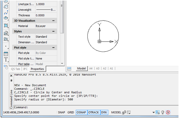
As an example, let’s write a single-item drop-down menu MyTest.cfg (with the Notepad text editor) that creates a round hole of radius 500 in the center point 700,600 in a drawing with the CIRCLE command. The dialog in the command line of such macro is shown in Fig. 1. The user must click on the menu item only one time without the need to enter any other data.
Fig. 1. The result of executing a complex menu macro
To create such a menu, you must fill in the menu and commands sections in the MyTest.cfg file:
[\]
[\menu]
[\menu\MyTest]
Name=sMyTest
[\menu\MyTest\MenuItem500]
Name=sHole_R500
Intername=sMHole500
[\configman]
[\configman\commands]
[\configman\commands\MHole500]
Weight=i30
CmdType=i1
Intername=sMHole500
LocalName=sHole_R500
DispName=sInsert_a_hole_R500
StatusText=sAdd a hole R500
ToolTipText=sHole R500
Keyword=s_.CIRCLE;700,600;500;
IsUserCommand=f1
This file includes the description of the new MHole500 command with such macro (the s character before is a special one):
_.CIRCLE;700,600;500;
This macro includes the CIRCLE command and two parameters: 700,600 (the center point coordinates) and 500 (the radius value), which are separated by a semicolon (the equivalent of pressing Enter when running on the command line).
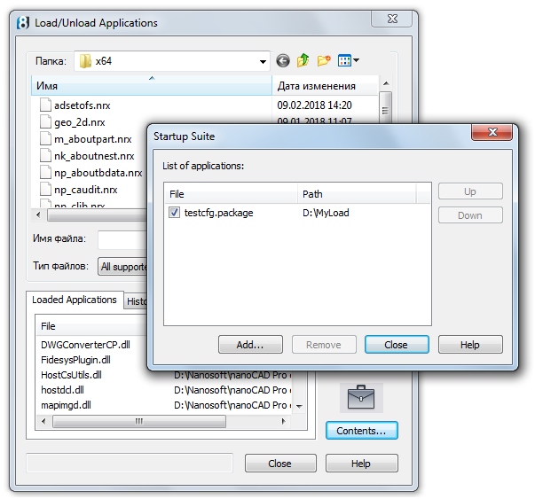
To simplify loading this menu, let us use the testcfg.package packet file, specifying its name in the startup suite. To do this, select the menu item Tools > Application > Load application, and in the Load/Unload Applications, click on the Contents button under the briefcase image (Fig. 2).
Fig. 2. Autoloading testcfg.package using the suite
In the Startup Suite child window, using the Add button, add the testcfg.package file to the list of autoloaded files. Save this file before in the D:\MyLoad folder side by side with MyTest.cfg side by side with MyTest,cfg. In the testcfg.package file, which is a XML-file in UTF-8 encoding (it is important!), write the following:
<?xml version=”1.0″ encoding=”utf-8″ ?>
<ApplicationPackage
xmlns=”hostModulePackage/v01″
Name=”Tests”
>
<Components>
<ConfigEntry
FileName=”MyTest.cfg”
FileType=”CFG”
/>
</Components>
</ApplicationPackage>
Here, in the ConfigEntry tag, specify the data about the CFG file, which must be loaded immediately after loading the main nanoCAD core (there must be several tags, if you want to load several CFG files). For more details about .package files, see the article Customizing the User Interface When Installing Apps For nanoCAD Plus 8.5“.
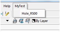
After closing the Startup Suite and Load/Unload Applications and restarting nanoCAD, you will see our MyTest menu in the menu bar (Fig. 3):
Fig. 3. MyTest in the menu bar
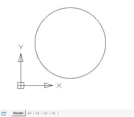
The dropdown menu includes one item which creates a circle with a fixed radius and a fixed center (Fig. 4):
Fig. 4. The circle drawn
The macro we wrote is a complex one (it includes three parts). But it implements a very simple option. Let us expand the task: allow the user himself or herself specify the center point.
Pause in the menu
The 8.5 version, the function of pause processing in macros has been added. To illustrate this, let us copy the MyTest.cfg file in MyTest1.cfg; rename the MHole500 command to M1Hole500, and change the macro text in the Keyword parameter:
[\configman\commands\M1Hole500]
weight=i30
CmdType=i1
Intername=sM1Hole500
LocalName=sHole_R500
DispName=sInsert_a_hole_R500
StatusText=sAdd a hole R500
ToolTipText=sHole R500
Keyword=s_.CIRCLE;\500;
IsUserCommand=f1
The macro is as follows:
_.CIRCLE;\500;
As compared with the macro in the previous example, there is no center, but there is back slash (\). This is a pause signal for user input (there, the CIRCLE command requests the center point).
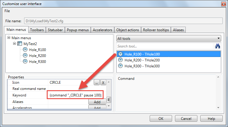
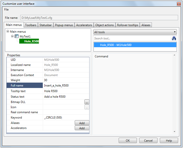
Fig. 5 shows how our macro looks like if we load the MyTest1.cfg file into the interface editor using the INTERFACE command (or using the menu item Tools > Customize> Interface) and select the MyTest1.cfg file using File > Open.
Fig. 5. Displaying a macro with a pause symbol in the interface editor
In the Properties pane, the macro text is shown in the Keyword parameter.
Important note. When you save menu files in the interface editor, they replace the main menu of the nanoCAD platform. To return to the previous main menu, use the SETCONFIG command or edit manually the file c:\Users\user\AppData\Roaming\Nanosoft\nanoCAD [x64] Pro Int 8.5\Config\cfg.ini.
Let us edit the testcfg.package file (you can add the MyTest1.cfg menu in it). Here is an exemplary result of running the macro (Fig. 6):
Fig. 6. Running a macro including a pause character
LISP expressions in the menu
Processing LISP expressions in the command line is another step forward in nanoCAD 8.5. At the same time, it is possible to include LISP expressions in the macro menu.
For example, let us write another variant of the menu (MyTest2.cfg), but already including three items that implement creating round holes in the drawing using the CIRCLE command. The commands must run through LISP expressions. The menu items will differ only in their radius values (100, 200, and 300). There, the hole center point will be requested using a pause (the PAUSE LISP symbol). At the same time, let us complicate the menu items adding a standard icon of the CIRCLE command. The system icons are in the newbtns.dll file which is part of the nanoCAD software. The icon name is the same as the command name.
[\]
[\menu]
[\menu\MyTest2]
Name=sMyTest2
[\menu\MyTest2\MenuItem100]
Name=sHole_R100
Intername=sTHole100
[\menu\MyTest2\MenuItem200]
Name=sHole_R200
Intername=sTHole200
[\menu\MyTest2\MenuItem300]
Name=sHole_R300
Intername=sTHole300
[\configman]
[\configman\commands]
[\configman\commands\THole100]
Weight=i30
CmdType=i1
Intername=sTHole100
LocalName=sHole_R100
DispName=sInsert_a_hole_R100
StatusText=sAdd a hole R100
ToolTipText=sHole R100
BitmapDll=snewbtns.dll
Icon=sCIRCLE
Keyword=s(command “_.CIRCLE” pause 100);
IsUserCommand=f1
[\configman\commands\THole200]
Weight=i30
CmdType=i1
Intername=sTHole200
LocalName=sHole_R200
DispName=sInsert_a_hole_R200
StatusText=sAdd a hole R200
ToolTipText=sHole R200
BitmapDll=snewbtns.dll
Icon=sCIRCLE
Keyword=s(command “_.CIRCLE” pause 200);
IsUserCommand=f1
[\configman\commands\THole300]
Weight=i30
CmdType=i1
Intername=sTHole300
LocalName=sHole_R300
DispName=sInsert_a_hole_R300
StatusText=sAdd a hole R300
ToolTipText=sHole R300
BitmapDll=snewbtns.dll
Icon=sCIRCLE
Keyword=s(command “_.CIRCLE” pause 300);
IsUserCommand=f1
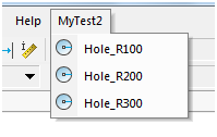
This file includes the description of three commands (THole100, THole200, THole300), that operate by running LISP expressions with a command function. See how the macros with a LISP expression looks like in the interface editor (in the figure, at the beginning of the article, the menu MyTest2.cfg is shown).
After completing the above operations with the startup suite and restarting nanoCAD, we will see our menu MyTest2 in the menu bar (Fig. 7):
Fig. 7. MyTest2 with three menu items
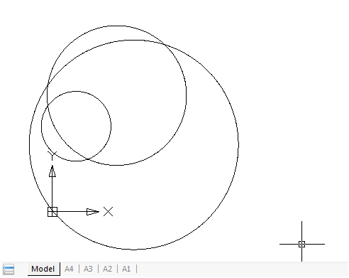
The drop-down menu includes three items that create circles with three radiuses (Fig. 8):
Fig. 8. The result of running three menu items
Transparent commands
In the nanoCAD system, some commands (such as ZOOM or PAN) can be run in a transparent mode, without interfering with other commands previously started. The 8.5 version implements running commands in a transparent mode from the command line with an apostrophe added before their names, by analogy with other CAD systems (Fig. 9):
Fig. 9. A transparent ‘ZOOM command entered in the command line
In this example, when running the LINE command, the ‘ZOOM command was run in a transparent mode with the E parameter (Zoom Extents), whereupon the control returns successfully back to the LINE command.
It is possible to include transparent commands in the menu macro, for example:
Keyword=s_.CIRCLE;’_.ZOOM;_E;\400;
The *.cuix converter to *.cfg
When exporting user menus from AutoCAD to nanoCAD, the CuixConverter.exe utility function can be used, ftp.nanocad.ru/habr/CUIX85/CuixConverter85.zip.
It reads a CUIX file and creates a corresponding CFG file. The syntax for using the converter (on the example of my.cuix):
CuixConverter.exe [<path>\]my.cuix
<path> may be absolute or relative (according to Windows rules). If the path is not specified, the file must be stored in the current folder. As a result of running the utility function, the my.cuix.cfg file with the conversion results will be created in the same <path> folder. This will save you from the painstaking work on writing CFG files manually or using the Tools > Customize > Interface command.
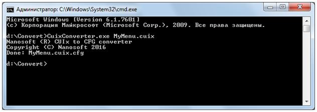
To run the converter, use the Windows command line console. It can be opened by typing cmd in the Windows run line. Here is an example of working with the MyMenu.cuix file, which is stored in the same folder as the converter files: *.exe, *.dll (Fig. 10):
Fig. 10. The Windows command line console with the result of running the converter
As a result of successful running, you will see the following message:
Done: MyMenu.cuix.cfg.
Nikolay Poleshchuk

